DTC CHECK / CLEAR 1. CHECK DTC (CHECK USING TECHSTREAM) (a) Connect the Techstream to the DLC3. (b) Turn the ignition switch to ON. (c) Turn the Techstream on. (d) Enter the following menus: Body Electrical / Navigation System / Trouble Codes. (e) Check for DTCs, and then write them down. (f) Check the details of the DTC(s). 2. CLEAR DTC (CLEAR USING TECHSTREAM) (a) Connect the Techstream to the DLC3. (b) Turn the ignition switch to ON. (c) Turn the Techstream on. (d) Enter the following menus: Body Electrical / Navigation System / Trouble Codes. (e) Clear the DTCs. 3. START DIAGNOSTIC MODE HINT:
(a) Start the engine. (b) While pressing and holding the "AUDIO" switch of the navigation receiver assembly, operate the light control switch: Off → Tail → Off → Tail → Off → Tail → Off. (c) Diagnostic mode starts and the "Service Menu" screen will be displayed. Service inspection starts automatically and the result will be displayed. 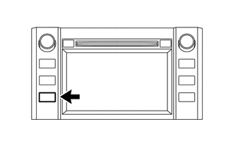 4. FAILURE DIAGNOSIS (a) The "Failure Diagnosis" screen will be displayed by pressing the "Failure Diagnosis" switch on the "Service Menu" screen. 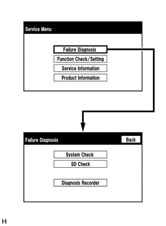 5. SYSTEM CHECK (a) The "System Check Mode" screen will be displayed by pressing the "System Check" switch on the "Failure Diagnosis" screen. 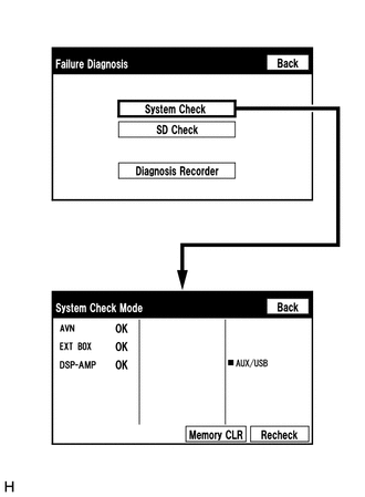 6. CHECK DTC (CHECK USING SYSTEM CHECK MODE SCREEN) HINT: When
"NCON" is displayed for all devices connected using the AVC-LAN, or
when all device names are not displayed, check if there is a short
circuit in the AVC-LAN or devices connected to the AVC-LAN. Repair or
replace parts as necessary (See page (a) System check mode screen description 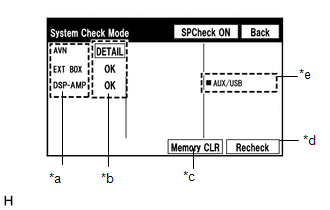 Screen Description Screen Description
(b) Unit check mode screen description 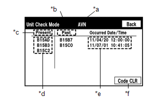 Screen Description Screen Description
HINT:
(c) Read the system check result. 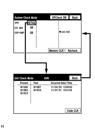 (1) If the check result is "DETAIL", touch the displayed check result to view the results on the "Unit Check Mode" screen and record them. NOTICE: A maximum of 6 DTCs can be displayed for history and present DTCs on the "Unit check mode" screen. Therefore, when 6 DTCs are displayed, troubleshoot those DTCs first and then check the "Unit check mode" screen again to see if any other DTCs are displayed. HINT:
(2) Check the details of the DTC(s) (See page
7. DTC CLEAR/RECHECK (CLEAR USING SYSTEM CHECK MODE SCREEN) (a) Clear DTCs 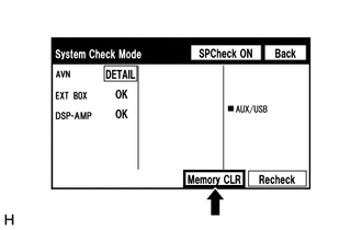 (1) Press the "Memory CLR" switch for 3 seconds. (2) Confirm that the check results are cleared. HINT:
(b) Recheck 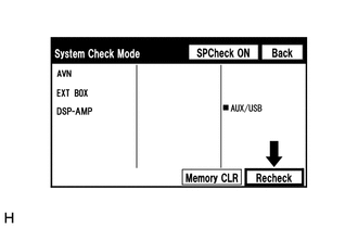 (1) Press the "Recheck" switch. (2) Confirm that all diagnostic codes are "OK" when the check results are displayed. If a code other than "OK" is displayed, troubleshoot again. 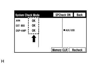 HINT: When the DTCs are cleared using the "Unit Check Mode" screen, press the "Back" switch to return to the "System Check Mode" screen and perform this operation. 8. FINISH DIAGNOSTIC MODE (a) Turn the ignition switch off. |
Toyota Tundra Service Manual > Seat Belt Warning System: Driver Side Seat Belt Warning Light does not Operate
DESCRIPTION The combination meter assembly illuminates, blinks or turns off the seat belt warning light on the combination meter assembly in accordance with the state of the front seat inner belt assembly LH. HINT: The seat belt warning light on the combination meter assembly is used for both the dr ...

 ).
).
