Toyota Tundra Service Manual: Navigation Receiver Assembly Power Source Circuit

DESCRIPTION

This circuit provides power to the navigation receiver assembly.

WIRING DIAGRAM

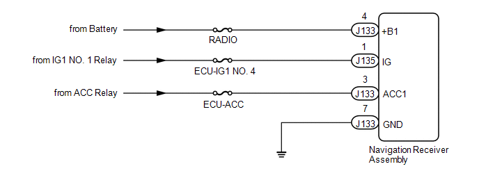
CAUTION / NOTICE / HINT

NOTICE:

Inspect the fuses for circuits related to this system before performing the following inspection procedure.

PROCEDURE

1.

CHECK HARNESS AND CONNECTOR (NAVIGATION RECEIVER ASSEMBLY - BATTERY AND BODY GROUND)

(a) Disconnect the navigation receiver assembly connectors.

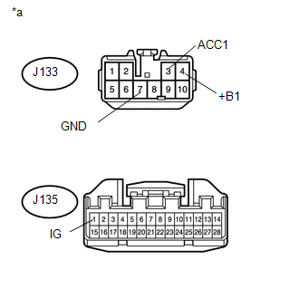
(b) Measure the resistance according to the value(s) in the table below.

Standard Resistance:

Tester Connection

Condition

Specified Condition

J133-7 (GND) - Body ground

Always

Below 1 Ω

(c) Measure the voltage according to the value(s) in the table below.

Standard Voltage:

Tester Connection

Condition

Specified Condition

J133-4 (+B1) - Body ground

Always

11 to 14 V

J133-3 (ACC1) - Body ground

Ignition switch ACC

11 to 14 V

J135-1 (IG) - Body ground

Ignition switch ON

11 to 14 V

Text in Illustration

*a

Front view of wire harness connector

(to Navigation Receiver Assembly)

OK

PROCEED TO NEXT SUSPECTED AREA SHOWN IN PROBLEM SYMPTOMS TABLE

NG

REPAIR OR REPLACE HARNESS OR CONNECTOR

    Mute Signal Circuit between Navigation Receiver Assembly and Stereo Component Amplifier

    Navigation Voice Circuit

    See More:

    Toyota Tundra Service Manual > Sfi System: Open in Secondary Air Injection System Heater Control Circuit (P144C,P144D)
    DESCRIPTION The ECM operates the air pump heater (AI HTR) relay which causes the air pump heater (AI HTR) to operate. DTC No. DTC Detection Condition Trouble Area P144C Open or short in the air pump heater (AI HTR) relay circuit for 5 seconds (1 trip detection logic). Open or short in air pump heate ...

    Toyota Tundra Owners Manual

    Toyota Tundra Service Manual

    © 2025 Copyright www.ttundra.com
    0.0119