DESCRIPTION This circuit is used when the voice guidance in the navigation system is on or an incoming cellular phone voice in the "Bluetooth" hands-free system is heard. Using this circuit, the navigation receiver assembly sends the signals to the stereo component amplifier assembly. WIRING DIAGRAM 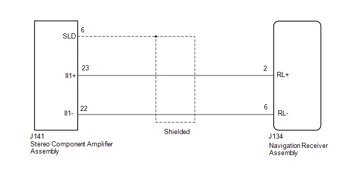 PROCEDURE
(a) Disconnect the J134 navigation receiver assembly connector. (b) Disconnect the J141 stereo component amplifier connector. (c) Measure the resistance according to the value(s) in the table below. Standard Resistance:
|
Toyota Tundra Service Manual > Window Defogger System: Problem Symptoms Table
PROBLEM SYMPTOMS TABLE HINT: Use the table below to help determine the cause of problem symptoms. If multiple suspected areas are listed, the potential causes of the symptoms are listed in order of probability in the "Suspected Area" column of the table. Check each symptom by checking the ...


