DESCRIPTION This circuit includes the parking brake switch assembly and navigation receiver assembly. WIRING DIAGRAM 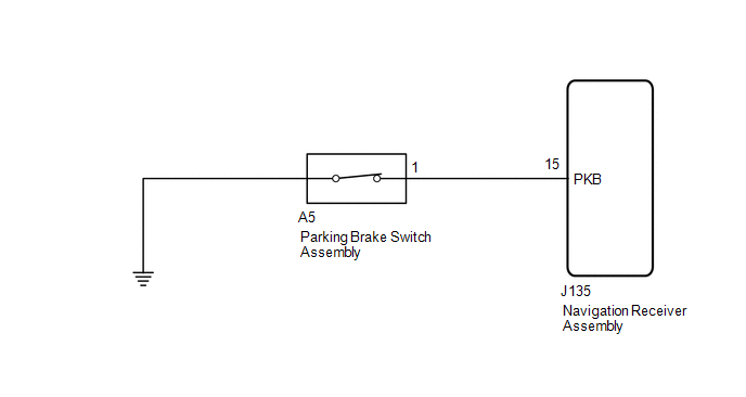 PROCEDURE
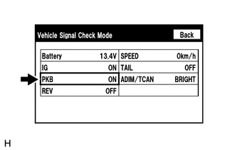
(b) Check that the display changes between ON and OFF according to the parking brake operation. OK:
HINT: This display is updated once per second. As a result, it is normal for the display to lag behind the actual parking brake operation.
(a) Disconnect the J135 navigation receiver assembly connector. (b) Disconnect the A5 parking brake switch assembly connector. (c) Measure the resistance according to the value(s) in the table below. Standard Resistance:
(a) Remove the parking brake switch assembly (See page
(b) Inspect the parking brake switch assembly (See page
|
Toyota Tundra Service Manual > Rear Axle Shaft: Installation
INSTALLATION PROCEDURE 1. INSTALL REAR AXLE SHAFT OIL SEAL (a) Using SST and a hammer, tap in a new oil seal. SST: 09950-60020 09951-00770 SST: 09950-70010 09951-07150 (b) Apply MP grease to the lip of the oil seal. NOTICE: Do not allow foreign matter, etc. to contact the axle shaft housing hole. 2. ...

 ).
).