DESCRIPTION The navigation receiver assembly receives a reverse signal from the park/neutral position switch assembly. WIRING DIAGRAM 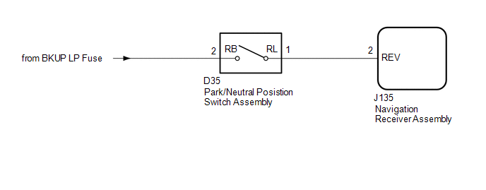 CAUTION / NOTICE / HINT NOTICE: Inspect the fuses for circuits related to this system before performing the following inspection procedure. PROCEDURE
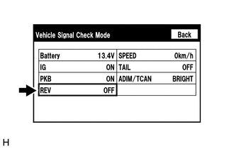
(b) Check that the display changes between ON and OFF according to the shift lever position. OK:
HINT: This display is updated once per second. As a result, it is normal for the display to lag behind the actual shift lever position.
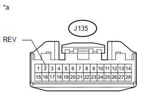 (a) Disconnect the navigation receiver assembly connector. (b) Measure the voltage according to the value(s) in the table below. Standard Voltage:
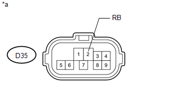
(a) Disconnect the J135 navigation receiver assembly connector. (b) Disconnect the D35 park/neutral position switch assembly connector. (c) Measure the resistance according to the value(s) in the table below. Standard Resistance:
(b) Measure the voltage according to the value(s) in the table below. Standard Voltage:
HINT: If replacing the park/neutral position switch assembly, refer to the procedures below.
|
Toyota Tundra Service Manual > Headlight Assembly(for Halogen Headlight): Installation
INSTALLATION CAUTION / NOTICE / HINT HINT: Use the same procedure for the RH and LH sides. The procedure listed below is for the LH side. A bolt without a torque specification is shown in the standard bolt chart (See page ). PROCEDURE 1. INSTALL HEADLIGHT ASSEMBLY LH (a) Put protective tape around t ...

 )].
)].