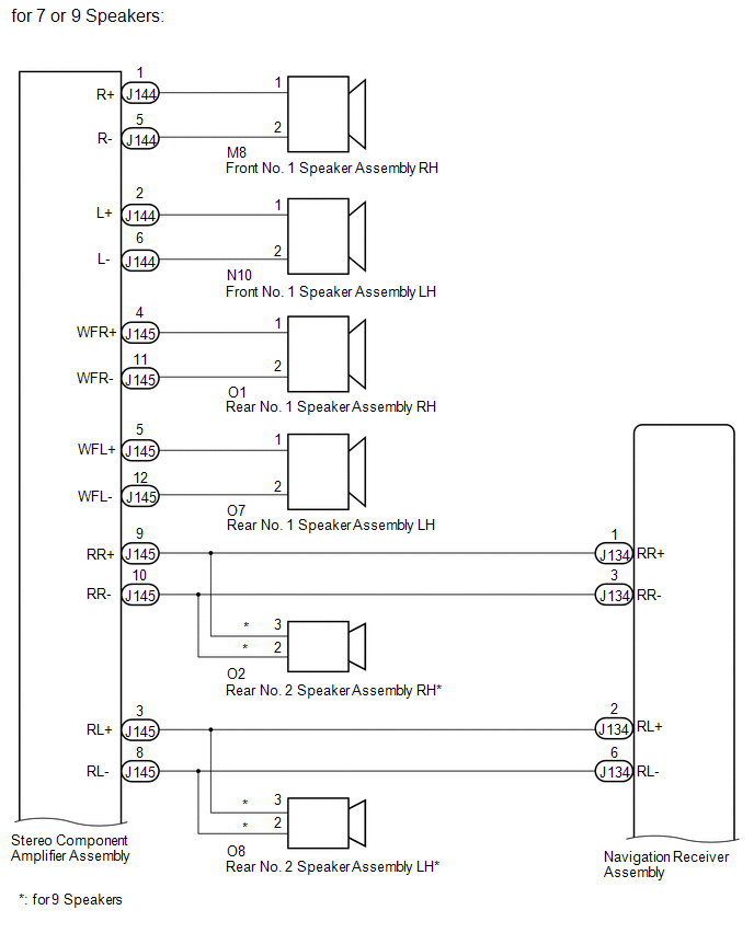
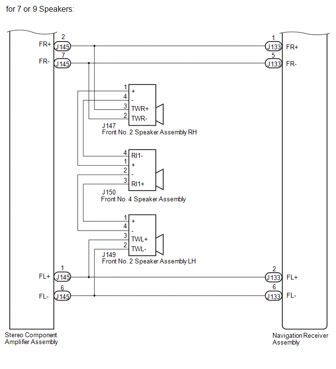
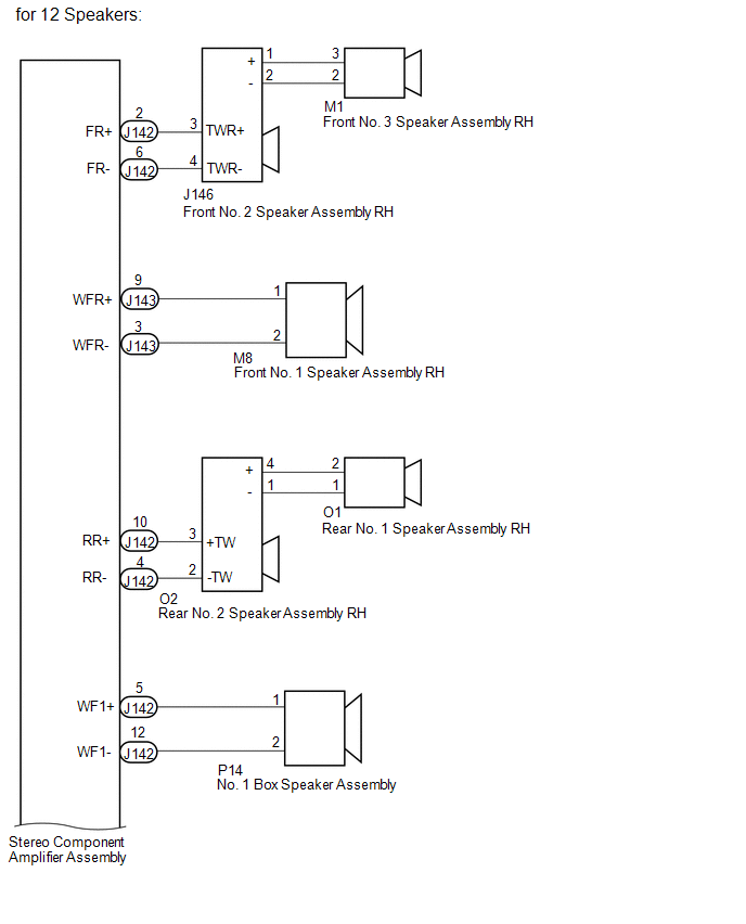
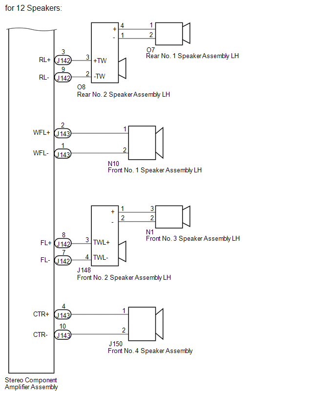
DESCRIPTION The navigation receiver assembly sends sound signals to the speakers. WIRING DIAGRAM
 PROCEDURE
| 1. |
CHECK VEHICLE CONDITION | (a) Check the vehicle condition. Result |
Result | Proceed to | |
for 7 or 9 Speakers | A | |
for 12 Speakers | B |
| B |
 | GO TO STEP 9 |
|
A |
 | |
| 2. |
CHECK HARNESS AND CONNECTOR (SPEAKER CIRCUIT) |
- *1: for RH Side
- *2: for LH Side
- *3: for 9 Speakers
(a) Disconnect the J133 and J134 navigation receiver assembly connector.
(b) Disconnect the M8*1 and/or N10*2 front No. 1 speaker assembly connector.
(c) Disconnect the J147*1 and/or J149*2 front No. 2 speaker assembly connector.
(d) Disconnect the J150 front No. 4 speaker assembly connector. (e) Disconnect the O1*1 and/or O7*2 rear No. 1 speaker assembly connector.
(f) Disconnect the O2*1 and/or O8*2 rear No. 2 speaker assembly connector.*3
(g) Disconnect the J144 and J145 stereo component amplifier assembly connectors.
(h) Measure the resistance according to the value(s) in the table below.
Standard Resistance: |
Tester Connection | Condition |
Specified Condition | |
M8-1 - J144-1 (R+) | Always |
Below 1 Ω | |
M8-2 - J144-5 (R-) | Always |
Below 1 Ω | |
N10-1 - J144-2 (L+) | Always |
Below 1 Ω | |
N10-2 - J144-6 (L-) | Always |
Below 1 Ω | |
O1-1 - J145-4 (WFR+) |
Always | Below 1 Ω | |
O1-2 - J145-11 (WFR-) |
Always | Below 1 Ω | |
O7-1 - J145-5 (WFL+) |
Always | Below 1 Ω | |
O7-2 - J145-12 (WFL-) |
Always | Below 1 Ω | |
O2-3 - J145-9 (RR+)*3 |
Always | Below 1 Ω | |
O2-2 - J145-10 (RR-)*3 |
Always | Below 1 Ω | |
J145-9 (RR+) - J134-1 (RR+) |
Always | Below 1 Ω | |
J145-10 (RR-) - J134-3 (RR-) |
Always | Below 1 Ω | |
O8-3 - J145-3 (RL+)*3 |
Always | Below 1 Ω | |
O8-2 - J145-8 (RL-)*3 |
Always | Below 1 Ω | |
J145-3 (RL+) - J134-2 (RL+) |
Always | Below 1 Ω | |
J145-8 (RL-) - J134-6 (RL-) |
Always | Below 1 Ω | |
J145-2 (FR+) - J133-1 (FR+) |
Always | Below 1 Ω | |
J145-7 (FR-) - J133-5 (FR-) |
Always | Below 1 Ω | |
J145-1 (FL+) - J133-2 (FL+) |
Always | Below 1 Ω | |
J145-6 (FL-) - J133-6 (FL-) |
Always | Below 1 Ω | |
J145-2 (FR+) - J147-3 (TWR+) |
Always | Below 1 Ω | |
J145-7 (FR-) - J147-2 (TWR-) |
Always | Below 1 Ω | |
J145-1 (FL+) - J149-3 (TWL+) |
Always | Below 1 Ω | |
J145-6 (FL-) - J149-2 (TWL-) |
Always | Below 1 Ω | |
J147-1 (+) - J150-1 (+) |
Always | Below 1 Ω | |
J147-4 (-) - J150-4 (RI1-) |
Always | Below 1 Ω | |
J150-2 (-) - J149-4 (-) |
Always | Below 1 Ω | |
J150-3 (RI1+) - J149-1 (+) |
Always | Below 1 Ω | |
J144-1 (R+) - Body ground |
Always | 10 kΩ or higher | |
J144-5 (R-) - Body ground |
Always | 10 kΩ or higher | |
J144-2 (L+) - Body ground |
Always | 10 kΩ or higher | |
J144-6 (L-) - Body ground |
Always | 10 kΩ or higher | |
J145-4 (WFR+) - Body ground |
Always | 10 kΩ or higher | |
J145-11 (WFR-) - Body ground |
Always | 10 kΩ or higher | |
J145-5 (WFL+) - Body ground |
Always | 10 kΩ or higher | |
J145-12 (WFL-) - Body ground |
Always | 10 kΩ or higher | |
J145-9 (RR+) - Body ground |
Always | 10 kΩ or higher | |
J145-10 (RR-) - Body ground |
Always | 10 kΩ or higher | |
J145-3 (RL+) - Body ground |
Always | 10 kΩ or higher | |
J145-8 (RL-) - Body ground |
Always | 10 kΩ or higher | |
J145-2 (FR+) - Body ground |
Always | 10 kΩ or higher | |
J145-7 (FR-) - Body ground |
Always | 10 kΩ or higher | |
J145-1 (FL+) - Body ground |
Always | 10 kΩ or higher | |
J145-6 (FL-) - Body ground |
Always | 10 kΩ or higher | |
J147-1 (+) - Body ground |
Always | 10 kΩ or higher | |
J147-4 (-) - Body ground |
Always | 10 kΩ or higher | |
J147-3 (TWR+) - Body ground |
Always | 10 kΩ or higher | |
J147-2 (TWR-) - Body ground |
Always | 10 kΩ or higher | |
J150-2 (-) - Body ground |
Always | 10 kΩ or higher | |
J150-3 (RI1+) - Body ground |
Always | 10 kΩ or higher | |
J149-3 (TWL+) - Body ground |
Always | 10 kΩ or higher | |
J149-2 (TWL-) - Body ground |
Always | 10 kΩ or higher |
| NG |
| REPAIR OR REPLACE HARNESS OR CONNECTOR |
|
OK | |
| |
| 3. |
INSPECT FRONT NO. 1 SPEAKER ASSEMBLY | (a) Remove the front No. 1 speaker assembly.
- for Double Cab: See page

- for CrewMax: See page
(b) Inspect the front No. 1 speaker assembly.
- for Double Cab: See page
- for CrewMax: See page
Result |
Result | Proceed to | |
OK | A | |
NG (for Double Cab) | B | |
NG (for CrewMax) | C |
| B |
| REPLACE FRONT NO. 1 SPEAKER ASSEMBLY |
| C |
| REPLACE FRONT NO. 1 SPEAKER ASSEMBLY |
|
A | |
| |
| 4. |
CHECK FRONT NO. 2 SPEAKER ASSEMBLY | (a) Replace the front No. 2 speaker assembly with a known good one.
- for Double Cab: See page
- for CrewMax: See page
(b) Check that the malfunction disappears.
NOTICE:
- Connect all the connectors to the front No. 2 speaker assemblies that were disconnected.
- Connect all the connectors to the front No. 2 speaker assemblies that were disconnected.
- Perform the above inspection on both LH and RH sides.
OK: Malfunction disappears.
| OK |
| END (FRONT NO. 2 SPEAKER ASSEMBLY IS DEFECTIVE) |
|
NG | |
| |
| 5. |
CHECK FRONT NO. 4 SPEAKER ASSEMBLY | (a) Replace the front No. 4 speaker assembly with a known good one.
- for Double Cab: See page
- for CrewMax: See page
(b) Check that the malfunction disappears. OK: Malfunction disappears.
| OK |
| END (FRONT NO. 4 SPEAKER ASSEMBLY IS DEFECTIVE) |
|
NG | |
| |
| 6. |
INSPECT REAR NO. 1 SPEAKER ASSEMBLY | (a) Remove the rear No. 1 speaker assembly with a known good one.
- for Double Cab: See page
- for CrewMax: See page
(b) Inspect the rear No. 1 speaker assembly with a known good one.
- for Double Cab: See page
- for CrewMax: See page
Result |
Result | Proceed to | |
OK (for CrewMax) | A | |
OK (for Double Cab) | B | |
NG (for Double Cab) | C | |
NG (for CrewMax) | D |
| B |
| GO TO STEP 8 |
| C |
| REPLACE REAR NO. 1 SPEAKER ASSEMBLY |
| D |
| REPLACE REAR NO. 1 SPEAKER ASSEMBLY |
|
A | |
| |
| 7. |
CHECK REAR NO. 2 SPEAKER ASSEMBLY | (a) Replace the rear No. 2 speaker assembly with a known good one (See page
). (b) Check that the malfunction disappears.
NOTICE:
- Connect all the connectors to the rear No. 2 speaker assemblies that were disconnected.
- Connect all the connectors to the rear No. 2 speaker assemblies that were disconnected.
- Perform the above inspection on both LH and RH sides.
OK: Malfunction disappears.
| OK |
| END (REAR NO. 2 SPEAKER ASSEMBLY IS DEFECTIVE) |
|
NG | |
| |
| 8. |
CHECK STEREO COMPONENT AMPLIFIER ASSEMBLY |
(a) Replace the stereo component amplifier assembly with a known good one (See page
). (b) Check that the malfunction disappears.
OK: Malfunction disappears. Result |
Result | Proceed to | |
OK | A | |
NG (for Column Shift Type) |
B | | NG (for Floor Shift Type) |
C |
| A |
| END (STEREO COMPONENT AMPLIFIER ASSEMBLY IS DEFECTIVE) |
| B |
| REPLACE NAVIGATION RECEIVER ASSEMBLY |
| C |
| REPLACE NAVIGATION RECEIVER ASSEMBLY |
| 9. |
CHECK HARNESS AND CONNECTOR (SPEAKER CIRCUIT) |
- *1: for RH Side
- *2: for LH Side
(a) Disconnect the M8*1 and/or N10*2 front No. 1 speaker assembly connector.
(b) Disconnect the J146*1 and/or J148*2 front No. 2 speaker assembly connector.
(c) Disconnect the M1*1 and/or N1*2 front No. 3 speaker assembly connector.
(d) Disconnect the J150 front No. 4 speaker assembly connector. (e) Disconnect the O1*1 and/or O7*2 rear No. 1 speaker assembly connector.
(f) Disconnect the O2*1 and/or O8*2 rear No. 2 speaker assembly connector.
(g) Disconnect the P14 No. 1 box speaker assembly connector. (h) Disconnect the J142 and J143 stereo component amplifier assembly connectors.
(i) Measure the resistance according to the value(s) in the table below.
Standard Resistance: |
Tester Connection | Condition |
Specified Condition | |
J142-2 (FR+) - J146-3 (TWR+) |
Always | Below 1 Ω | |
J142-6 (FR-) - J146-4 (TWR-) |
Always | Below 1 Ω | |
J146-1 (+) - M1-3 | Always |
Below 1 Ω | |
J146-2 (-) - M1-2 | Always |
Below 1 Ω | |
J143-9 (WFR+) - M8-1 |
Always | Below 1 Ω | |
J143-3 (WFR-) - M8-2 |
Always | Below 1 Ω | |
J142-10 (RR+) - O2-3 (+TW) |
Always | Below 1 Ω | |
J142-4 (RR-) - O2-2 (-TW) |
Always | Below 1 Ω | |
O2-4 (+) - O1-1 | Always |
Below 1 Ω | |
O2-1 (-) - O1-2 | Always |
Below 1 Ω | |
J143-5 (WF1+) - P14-1 |
Always | Below 1 Ω | |
J143-12 (WF1-) - P14-2 |
Always | Below 1 Ω | |
J142-3 (RL+) - O8-3 (+TW) |
Always | Below 1 Ω | |
J142-9 (RL-) - O8-2 (-TW) |
Always | Below 1 Ω | |
O8-4 (+) - O7-1 | Always |
Below 1 Ω | |
O8-1 (-) - O7-2 | Always |
Below 1 Ω | |
J143-2 (WFL+) - N10-1 |
Always | Below 1 Ω | |
J143-1 (WFL-) - N10-2 |
Always | Below 1 Ω | |
J142-8 (FL+) - J148-3 (TWL+) |
Always | Below 1 Ω | |
J142-7 (FL-) - J148-4 (TWL-) |
Always | Below 1 Ω | |
J148-1 (+) - N1-3 | Always |
Below 1 Ω | |
J148-2 (-) - N1-2 | Always |
Below 1 Ω | |
J143-4 (CTR+) - J150-1 |
Always | Below 1 Ω | |
J143-10 (CTR-) - J150-2 |
Always | Below 1 Ω | |
J142-2 (FR+) - Body ground |
Always | 10 kΩ or higher | |
J142-6 (FR-) - Body ground |
Always | 10 kΩ or higher | |
J146-1 (+) - Body ground |
Always | 10 kΩ or higher | |
J146-2 (-) - Body ground |
Always | 10 kΩ or higher | |
J143-9 (WFR+) - Body ground |
Always | 10 kΩ or higher | |
J143-3 (WFR-) - Body ground |
Always | 10 kΩ or higher | |
J142-10 (RR+) - Body ground |
Always | 10 kΩ or higher | |
J142-4 (RR-) - Body ground |
Always | 10 kΩ or higher | |
O2-4 (+) - Body ground |
Always | 10 kΩ or higher | |
O2-1 (-) - Body ground |
Always | 10 kΩ or higher | |
J143-5 (WF1+) - Body ground |
Always | 10 kΩ or higher | |
J143-12 (WF1-) - Body ground |
Always | 10 kΩ or higher | |
J142-3 (RL+) - Body ground |
Always | 10 kΩ or higher | |
J142-9 (RL-) - Body ground |
Always | 10 kΩ or higher | |
O8-4 (+) - Body ground |
Always | 10 kΩ or higher | |
O8-1 (-) - Body ground |
Always | 10 kΩ or higher | |
J143-2 (WFL+) - Body ground |
Always | 10 kΩ or higher | |
J143-1 (WFL-) - Body ground |
Always | 10 kΩ or higher | |
J142-8 (FL+) - Body ground |
Always | 10 kΩ or higher | |
J142-7 (FL-) - Body ground |
Always | 10 kΩ or higher | |
J148-1 (+) - Body ground |
Always | 10 kΩ or higher | |
J148-2 (-) - Body ground |
Always | 10 kΩ or higher | |
J143-4 (CTR+) - Body ground |
Always | 10 kΩ or higher | |
J143-10 (CTR-) - Body ground |
Always | 10 kΩ or higher |
| NG |
| REPAIR OR REPLACE HARNESS OR CONNECTOR |
|
OK | |
| |
| 10. |
INSPECT FRONT NO. 1 SPEAKER ASSEMBLY | (a) Remove the front No. 1 speaker assembly (See page
). (b) Inspect the front No. 1 speaker assembly (See page
).
| NG | |
REPLACE FRONT NO. 1 SPEAKER ASSEMBLY |
|
OK | |
| |
| 11. |
CHECK FRONT NO. 2 SPEAKER ASSEMBLY | (a) Replace the front No. 2 speaker assembly with a known good one (See page
). (b) Check that the malfunction disappears.
NOTICE:
- Connect all the connectors to the front No. 2 speaker assemblies that were disconnected.
- Connect all the connectors to the front No. 2 speaker assemblies that were disconnected.
- Perform the above inspection on both LH and RH sides.
OK: Malfunction disappears.
| OK |
| END (FRONT NO. 2 SPEAKER ASSEMBLY IS DEFECTIVE) |
|
NG | |
| |
| 12. |
CHECK FRONT NO. 4 SPEAKER ASSEMBLY | (a) Replace the front No. 4 speaker assembly with a known good one (See page
). (b) Check that the malfunction disappears.
OK: Malfunction disappears.
| OK |
| END (FRONT NO. 4 SPEAKER ASSEMBLY IS DEFECTIVE) |
|
NG | |
| |
| 13. |
CHECK FRONT NO. 3 SPEAKER ASSEMBLY | (a) Replace the front No. 3 speaker assembly with a known good one (See page
). (b) Check that the malfunction disappears.
NOTICE:
- Connect all the connectors to the front No. 3 speaker assemblies that were disconnected.
- Connect all the connectors to the front No. 3 speaker assemblies that were disconnected.
- Perform the above inspection on both LH and RH sides.
OK: Malfunction disappears.
| OK |
| END (FRONT NO. 3 SPEAKER ASSEMBLY IS DEFECTIVE) |
|
NG | |
| |
| 14. |
INSPECT NO. 1 BOX SPEAKER ASSEMBLY | (a) Remove the No. 1 box speaker assembly (See page
). (b) Inspect the No. 1 box speaker assembly (See page
).
| NG | |
REPLACE NO. 1 BOX SPEAKER ASSEMBLY |
|
OK | |
| |
| 15. |
INSPECT REAR NO. 1 SPEAKER ASSEMBLY | (a) Remove the rear No. 1 speaker assembly (See page
). (b) Inspect the rear No. 1 speaker assembly (See page
).
| NG | |
REPLACE REAR NO. 1 SPEAKER ASSEMBLY |
|
OK | |
| |
| 16. |
CHECK REAR NO. 2 SPEAKER ASSEMBLY | (a) Replace the rear No. 2 speaker assembly with a known good one (See page
). (b) Check that the malfunction disappears.
NOTICE:
- Connect all the connectors to the rear No. 2 speaker assemblies that were disconnected.
- Connect all the connectors to the rear No. 2 speaker assemblies that were disconnected.
- Perform the above inspection on both LH and RH sides.
OK: Malfunction disappears.
| OK |
| END (REAR NO. 2 SPEAKER ASSEMBLY IS DEFECTIVE) |
|
NG | |
| |
| 17. |
CHECK STEREO COMPONENT AMPLIFIER ASSEMBLY |
(a) Replace the stereo component amplifier assembly with a known good one (See page
). (b) Check that the malfunction disappears.
OK: Malfunction disappears. Result |
Result | Proceed to | |
OK | A | |
NG (for Column Shift Type) |
B | | NG (for Floor Shift Type) |
C |
| A |
| END (STEREO COMPONENT AMPLIFIER ASSEMBLY IS DEFECTIVE) |
| B |
| REPLACE NAVIGATION RECEIVER ASSEMBLY |
| C |
| REPLACE NAVIGATION RECEIVER ASSEMBLY | | 

