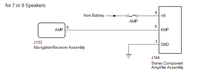
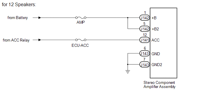
DESCRIPTION This circuit provides power to the stereo component amplifier assembly. WIRING DIAGRAM
 CAUTION / NOTICE / HINT
NOTICE: Inspect the fuses for circuits related to this system before performing the following inspection procedure. PROCEDURE
| 1. |
CHECK VEHICLE CONDITION | (a) Check the vehicle condition. Result |
Result | Proceed to | |
for 7 or 9 Speakers | A | |
for 12 Speakers | B |
| B |
 | GO TO STEP 4 |
|
A |
 | |
| 2. |
CHECK HARNESS AND CONNECTOR (STEREO COMPONENT AMPLIFIER ASSEMBLY - BATTERY AND BODY GROUND) |
| (a) Disconnect the stereo component amplifier assembly connector. |
|
(b) Measure the resistance according to the value(s) in the table below.
Standard Resistance: |
Tester Connection | Condition |
Specified Condition | |
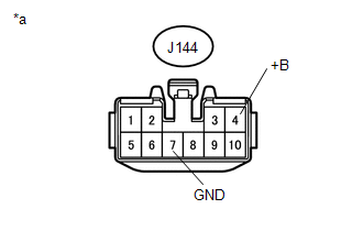
J144-7 (GND) - Body ground |
Always | Below 1 Ω |
(c) Measure the voltage according to the value(s) in the table below. Standard Voltage: |
Tester Connection | Condition |
Specified Condition | |
J144-4 (+B) - Body ground |
Always | 11 to 14 V | Text in Illustration |
*a | Front view of wire harness connector
(to Stereo Component Amplifier Assembly) |
| NG |
| REPAIR OR REPLACE HARNESS OR CONNECTOR |
|
OK | |
| |
| 3. |
CHECK HARNESS AND CONNECTOR (STEREO COMPONENT AMPLIFIER ASSEMBLY - NAVIGATION RECEIVER ASSEMBLY) |
(a) Disconnect the J144 stereo component amplifier assembly connector.
(b) Disconnect the J133 navigation receiver assembly connector. (c) Measure the resistance according to the value(s) in the table below.
Standard Resistance: |
Tester Connection | Condition |
Specified Condition | |
J144-9 (AMP) - J133-9 (AMP) |
Always | Below 1 Ω | |
J144-9 (AMP) - Body ground |
Always | 10 kΩ or higher |
| OK |
| PROCEED TO NEXT SUSPECTED AREA SHOWN IN PROBLEM SYMPTOMS TABLE |
| NG |
| REPAIR OR REPLACE HARNESS OR CONNECTOR |
| 4. |
CHECK HARNESS AND CONNECTOR (STEREO COMPONENT AMPLIFIER ASSEMBLY - BATTERY AND BODY GROUND) |
| (a) Disconnect the stereo component amplifier assembly connectors. |
|
(b) Measure the resistance according to the value(s) in the table below.
Standard Resistance: |
Tester Connection | Condition |
Specified Condition | |
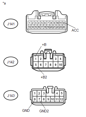
J143-6 (GND) - Body ground |
Always | Below 1 Ω | |
J143-7 (GND2) - Body ground |
Always | Below 1 Ω |
(c) Measure the voltage according to the value(s) in the table below. Standard Voltage: |
Tester Connection | Condition |
Specified Condition | |
J142-1 (+B) - J143-6 (GND) |
Always | 11 to 14 V | |
J142-5 (+B2) - J143-6 (GND) |
Always | 11 to 14 V | |
J141-12 (ACC) - J143-6 (GND) |
Ignition switch ACC | 11 to 14 V | Text in Illustration |
*a | Front view of wire harness connector
(to Stereo Component Amplifier Assembly) |
| OK |
| PROCEED TO NEXT SUSPECTED AREA SHOWN IN PROBLEM SYMPTOMS TABLE |
| NG |
| REPAIR OR REPLACE HARNESS OR CONNECTOR | |