Toyota Tundra Service Manual: Short to GND in Outer Mirror Indicator(Master) (C1AB2)

DESCRIPTION

This DTC is stored when the blind spot monitor sensor RH detects a short to ground in the outer rear view mirror indicator RH.

DTC No.

DTC Detection Condition

Trouble Area

C1AB2

Both of the following conditions are met:
  • The blind spot monitor system is on
  • The current that is sent from the blind spot monitor sensor to the indicator is above a specified level for a specified period of time
  • Outer rear view mirror sub-assembly RH
  • Outer rear view mirror assembly RH
  • Harness or connector
  • Blind spot monitor sensor RH

WIRING DIAGRAM

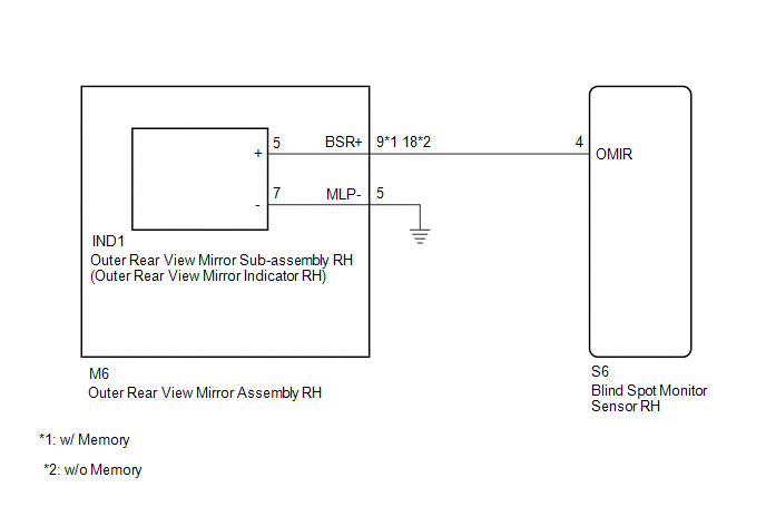
CAUTION / NOTICE / HINT

NOTICE:

When checking for DTCs, make sure that the blind spot monitor system is turned on.

PROCEDURE

1.

CHECK DTC

(a) Clear the DTCs.

Click here

(b) Recheck for DTCs and check if the same DTC is output again.

Click here

OK:

No DTCs are output.

OK

USE SIMULATION METHOD TO CHECK

NG

2.

CHECK HARNESS AND CONNECTOR (BLIND SPOT MONITOR SENSOR RH - OUTER REAR VIEW MIRROR ASSEMBLY RH)

(a) Disconnect the S6 blind spot monitor sensor RH connector.

*a

Front view of wire harness connector

(to Blind Spot Monitor Sensor RH)

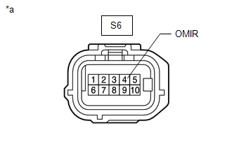
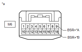
(b) Disconnect the M6 outer rear view mirror assembly RH connector.

(c) Measure the resistance according to the value(s) in the table below.

Standard Resistance:

Tester Connection

Condition

Always

S6-4 (OMIR) - Body ground or other terminal

Always

10 kΩ or higher

NG

REPAIR OR REPLACE HARNESS OR CONNECTOR

OK

3.

INSPECT OUTER REAR VIEW MIRROR ASSEMBLY RH

(a) Disconnect the M6 outer rear view mirror assembly RH connector.

*A

w/ Memory

*B

w/o Memory

*a

Component without harness connected

(Outer Rear View Mirror Assembly RH)

(b) Disconnect the IND1 outer rear view mirror sub-assembly RH connector.

(c) Measure the resistance according to the value(s) in the table below.

Standard Resistance:

w/ Memory

Tester Connection

Condition

Always

M6-9 (BSR+) - Body ground or other terminal

Always

10 kΩ or higher

w/o Memory

Tester Connection

Condition

Always

M6-18 (BSR+) - Body ground or other terminal

Always

10 kΩ or higher

NG

REPLACE OUTER REAR VIEW MIRROR ASSEMBLY RH

OK

4.

INSPECT OUTER REAR VIEW MIRROR SUB-ASSEMBLY RH

(a) Remove the outer rear view mirror sub-assembly RH.

Click here

(b) Inspect the outer rear view mirror indicator RH on the outer rear view mirror sub-assembly RH.

Click here

OK

REPLACE BLIND SPOT MONITOR SENSOR RH

NG

REPLACE OUTER REAR VIEW MIRROR SUB-ASSEMBLY RH

    Short to +B in Outer Mirror Indicator(Slave) (C1AB1)

    Short to GND in Outer Mirror Indicator(Slave) (C1AB3)

    See More:

    Toyota Tundra Service Manual > Lin Communication System: Front Passenger Side Door ECU Communication Stop (B2322)
    DESCRIPTION This DTC is stored when LIN communication between the front power window regulator motor assembly RH and main body ECU (multiplex network body ECU) stops for 10 seconds or more. DTC No. DTC Detection Condition Trouble Area B2322 No communication between the front power window regulator m ...

    Toyota Tundra Owners Manual

    Toyota Tundra Service Manual

    © 2025 Copyright www.ttundra.com
    0.0315