Toyota Tundra Service Manual: Short to GND in Outer Mirror Indicator(Slave) (C1AB3)

DESCRIPTION

This DTC is stored when the blind spot monitor sensor LH detects a short to ground in the outer rear view mirror indicator LH.

DTC No.

DTC Detection Condition

Trouble Area

C1AB3

Both of the following conditions are met:
  • The blind spot monitor system is on
  • The current that is sent from the blind spot monitor sensor to the indicator is above a specified level for a specified period of time
  • Outer rear view mirror sub-assembly LH
  • Outer rear view mirror assembly LH
  • Harness or connector
  • Blind spot monitor sensor LH

WIRING DIAGRAM

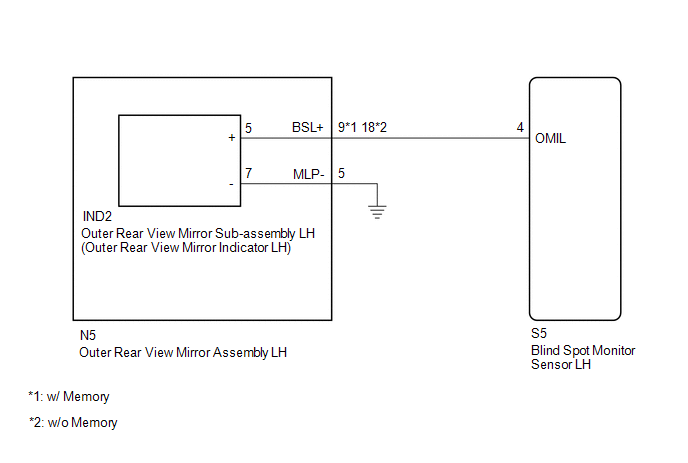
CAUTION / NOTICE / HINT

NOTICE:

When checking for DTCs, make sure that the blind spot monitor system is turned on.

PROCEDURE

1.

CHECK DTC

(a) Clear the DTCs.

Click here

(b) Recheck for DTCs and check if the same DTC is output again.

Click here

OK:

No DTCs are output.

OK

USE SIMULATION METHOD TO CHECK

NG

2.

CHECK HARNESS AND CONNECTOR (BLIND SPOT MONITOR SENSOR LH - OUTER REAR VIEW MIRROR ASSEMBLY LH)

(a) Disconnect the S5 blind spot monitor sensor LH connector.

*a

Front view of wire harness connector

(to Blind Spot Monitor Sensor LH)

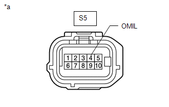
(b) Disconnect the N5 outer rear view mirror assembly LH connector.

(c) Measure the resistance according to the value(s) in the table below.

Standard Resistance:

Tester Connection

Condition

Specified Condition

S5-4 (OMIL) - Body ground or other terminal

Always

10 kΩ or higher

NG

REPAIR OR REPLACE HARNESS OR CONNECTOR

OK

3.

INSPECT OUTER REAR VIEW MIRROR ASSEMBLY LH

(a) Disconnect the N5 outer rear view mirror assembly LH connector.

*A

w/ Memory

*B

w/o Memory

*a

Component without harness connected

(Outer Rear View Mirror Assembly LH)

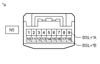
(b) Disconnect the IND2 outer rear view mirror sub-assembly LH connector.

(c) Measure the resistance according to the value(s) in the table below.

Standard Resistance:

w/ Memory

Tester Connection

Condition

Specified Condition

N5-9 (BSL+) - Body ground or other terminal

Always

10 kΩ or higher

w/o Memory

Tester Connection

Condition

Specified Condition

N5-18 (BSL+) - Body ground or other terminal

Always

10 kΩ or higher

NG

REPLACE OUTER REAR VIEW MIRROR ASSEMBLY LH

OK

4.

INSPECT OUTER REAR VIEW MIRROR SUB-ASSEMBLY LH

(a) Remove the outer rear view mirror sub-assembly LH.

Click here

(b) Inspect the outer rear view mirror indicator LH on the outer rear view mirror sub-assembly LH.

Click here

OK

REPLACE BLIND SPOT MONITOR SENSOR LH

NG

REPLACE OUTER REAR VIEW MIRROR SUB-ASSEMBLY LH

    Short to GND in Outer Mirror Indicator(Master) (C1AB2)

    Open in Outer Mirror Indicator(Master) (C1AB4)

    See More:

    Toyota Tundra Service Manual > Navigation System: Stereo Component Amplifier Power Source Circuit
    DESCRIPTION This circuit provides power to the stereo component amplifier assembly. WIRING DIAGRAM CAUTION / NOTICE / HINT NOTICE: Inspect the fuses for circuits related to this system before performing the following inspection procedure. PROCEDURE 1. CHECK VEHICLE CONDITION (a) Check the vehicle co ...

    Toyota Tundra Owners Manual

    Toyota Tundra Service Manual

    © 2024 Copyright www.ttundra.com
    0.0097