Toyota Tundra Service Manual: Open in Outer Mirror Indicator(Slave) (C1AB5)

DESCRIPTION

This DTC is stored when the blind spot monitor sensor LH detects an open in the outer rear view mirror indicator LH.
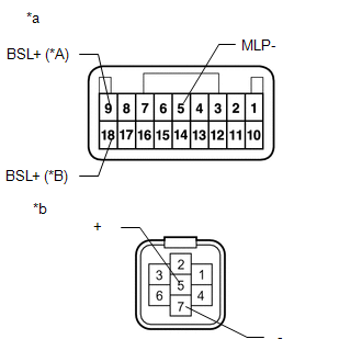
DTC No.

DTC Detection Condition

Trouble Area

C1AB5

Both of the following conditions are met:
  • The blind spot monitor system is on
  • The current flowing to the indicator is below a specified value when indicator operation voltage is being sent to the indicator
  • Outer rear view mirror sub-assembly LH
  • Outer rear view mirror assembly LH
  • Harness or connector
  • Blind spot monitor sensor LH

WIRING DIAGRAM

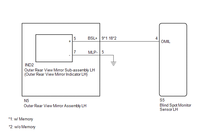
CAUTION / NOTICE / HINT

NOTICE:

When checking for DTCs, make sure that the blind spot monitor system is turned on.

PROCEDURE

1.

CHECK DTC

(a) Clear the DTCs.

Click here

(b) Recheck for DTCs and check if the same DTC is output again.

Click here

OK:

No DTCs are output.

OK

USE SIMULATION METHOD TO CHECK

NG

2.

CHECK HARNESS AND CONNECTOR (OUTER REAR VIEW MIRROR ASSEMBLY LH - BLIND SPOT MONITOR SENSOR LH AND BODY GROUND)

(a) Disconnect the S5 blind spot monitor sensor LH connector.

(b) Disconnect the N5 outer rear view mirror assembly LH connector.

(c) Measure the resistance according to the value(s) in the table below.

Standard Resistance:

w/ Memory

Tester Connection

Condition

Specified Condition

S5-4 (OMIL) - N5-9 (BSL+)

Always

Below 1 Ω

N5-5 (MLP-) - Body ground

Always

Below 1 Ω

w/o Memory

Tester Connection

Condition

Specified Condition

S5-4 (OMIL) - N5-18 (BSL+)

Always

Below 1 Ω

N5-5 (MLP-) - Body ground

Always

Below 1 Ω

NG

REPAIR OR REPLACE HARNESS OR CONNECTOR

OK

3.

INSPECT OUTER REAR VIEW MIRROR ASSEMBLY LH

(a) Disconnect the N5 outer rear view mirror assembly LH connector.

*A

w/ Memory

*B

w/o Memory

*a

Front view of outer rear view mirror assembly LH

(to Vehicle Harness Connector)

*b

Front view of outer rear view mirror assembly LH

(to Outer Rear View Mirror Sub-assembly LH)

(b) Disconnect the IND2 outer rear view mirror sub-assembly LH connector.

(c) Measure the resistance according to the value(s) in the table below.

Standard Resistance:

w/ Memory

Tester Connection

Condition

Specified Condition

N5-9 (BSL+) - IND2-5 (+)

Always

Below 1 Ω

N5-5 (MLP-) - IND2-7 (-)

Always

Below 1 Ω

w/o Memory

Tester Connection

Condition

Specified Condition

N5-18 (BSL+) - IND2-5 (+)

Always

Below 1 Ω

N5-5 (MLP-) - IND2-7 (-)

Always

Below 1 Ω

NG

REPLACE OUTER REAR VIEW MIRROR ASSEMBLY LH

OK

4.

INSPECT OUTER REAR VIEW MIRROR SUB-ASSEMBLY LH

(a) Remove the outer rear view mirror sub-assembly LH.

Click here

(b) Inspect the outer rear view mirror indicator LH on the outer rear view mirror sub-assembly LH.

Click here

OK

REPLACE BLIND SPOT MONITOR SENSOR LH

NG

REPLACE OUTER REAR VIEW MIRROR SUB-ASSEMBLY LH

    Open in Outer Mirror Indicator(Master) (C1AB4)

    Blind Spot Monitor Master Module (C1AB6)

    See More:

    Toyota Tundra Service Manual > Blind Spot Monitor System: System Description
    SYSTEM DESCRIPTION 1. GENERAL (a) The blind spot monitor system has the blind spot monitor function and RCTA function. (1) Blind spot monitor function The blind spot monitor function is a function that assists the driver in making the decision to change lanes. The function uses quasi-millimeter wave ...

    Toyota Tundra Owners Manual

    Toyota Tundra Service Manual

    © 2024 Copyright www.ttundra.com
    0.0255