PARTS LOCATION ILLUSTRATION 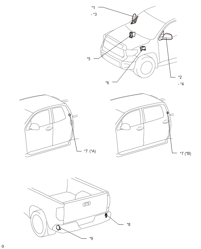
ILLUSTRATION 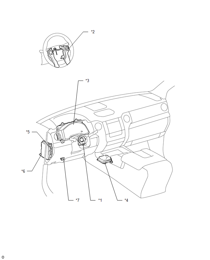
|
Toyota Tundra Service Manual > Power Door Lock Control System: Customize Parameters
CUSTOMIZE PARAMETERS PROCEDURE 1. CUSTOMIZE POWER DOOR LOCK CONTROL SYSTEM (a) Customizing with the Techstream HINT: The following items can be customized. NOTICE: When the customer requests a change in a function, first make sure that the function can be customized. Be sure to make a note of the cu ...


