DESCRIPTION The No. 3 ultrasonic sensor sends and receives ultrasonic waves. Based on the received wave, the sensor calculates the approximate distance value between the vehicle and the obstacle, and sends the distance value as a signal to the clearance warning ECU assembly. WIRING DIAGRAM 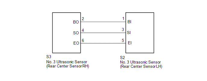 PROCEDURE
(a) Remove the No. 3 ultrasonic sensor (rear center sensor LH) (See page
(b) Inspect the No. 3 ultrasonic sensor (rear center sensor LH) (See page
(a) Disconnect the S2 No. 3 ultrasonic sensor (rear center sensor LH) connector. (b) Disconnect the S3 No. 3 ultrasonic sensor (rear center sensor RH) connector. (c) Measure the Resistance according to the value(s) in the table below. Standard Resistance:
|
Toyota Tundra Service Manual > Power Tilt And Power Telescopic Steering Column System: Diagnostic Trouble Code Chart
DIAGNOSTIC TROUBLE CODE CHART HINT: If a trouble code is displayed during the DTC check, inspect the trouble areas listed for that code. For details of the code, refer to "See page" below. Power Tilt and Power Telescopic Steering Column System DTC Code Detection Item DTC Detection Condition See page ...

 ).
).


