DESCRIPTION The No. 3 ultrasonic sensor sends and receives ultrasonic waves. Based on the received wave, the sensor calculates the approximate distance value between the vehicle and the obstacle, and sends the distance value as a signal to the clearance warning ECU assembly. WIRING DIAGRAM 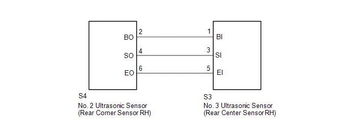 PROCEDURE
(a) Replace the No. 3 ultrasonic sensor (rear center sensor RH) (See page
(b) Inspect the No. 3 ultrasonic sensor (rear center sensor RH) (See page
(a) Disconnect the S3 No. 3 ultrasonic sensor (rear center sensor RH) connector. (b) Disconnect the S4 No. 2 ultrasonic sensor (rear corner sensor RH) connector. (c) Measure the resistance according to the value(s) in the table below. Standard Resistance:
|
Toyota Tundra Service Manual > Audio And Visual System: Sound of Portable Player cannot be Heard from Speakers or Sound is Low
PROCEDURE 1. CHECK PORTABLE PLAYER SETTINGS (a) Check the portable player settings. (1) Check that the volume is not set to "0". (2) Check that mute is off. (b) Check that the sound of the portable player can be heard from the speakers. OK: Sound of the portable player can be heard from the speakers ...

 ).
).


