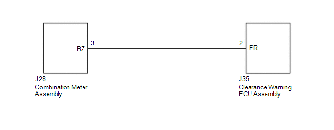
DESCRIPTION The clearance warning buzzer is installed in the combination meter assembly. WIRING DIAGRAM  PROCEDURE
(a) Disconnect the J35 clearance warning ECU assembly connector. (b) Disconnect the J28 combination meter assembly connector. (c) Measure the resistance according to the value(s) in the table below. Standard Resistance:
(a) Replace the combination meter assembly with a normally functioning or new one (See page
(b) Check that the clearance warning buzzer operates normally. OK: Clearance warning buzzer operates normally.
|
Toyota Tundra Service Manual > Spiral Cable: Removal
REMOVAL PROCEDURE 1. PRECAUTION NOTICE: After turning the ignition switch off, waiting time may be required before disconnecting the cable from the battery terminal. Therefore, make sure to read the disconnecting the cable from the battery terminal notice before proceeding with work (See page ). 2. ...