Toyota Tundra Service Manual: Clearance Warning ECU Power Source Circuit

DESCRIPTION

This circuit is the power source circuit to operate the clearance warning ECU assembly.

WIRING DIAGRAM

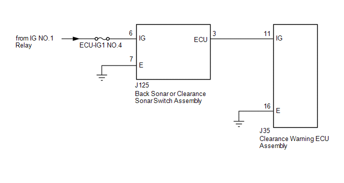
CAUTION / NOTICE / HINT

NOTICE:

Inspect the fuses for circuits related to this system before performing the following procedure.

PROCEDURE

1.

CHECK HARNESS AND CONNECTOR (BACK SONAR OR CLEARANCE SONAR SWITCH ASSEMBLY - BATTERY AND BODY GROUND)

(a) Disconnect the back sonar or clearance sonar switch assembly connector.

(b) Measure the voltage according to the value(s) in the table below.

Standard Voltage:

Tester Connection

Switch Condition

Specified Condition

J125-6 (IG) - Body ground

Ignition switch ON

11 to 14 V

Ignition switch off

Below 1 V

(c) Measure the resistance according to the value(s) in the table below.

Standard Resistance:

Tester Connection

Condition

Specified Condition

J125-7 (E) - Body ground

Always

Below 1 Ω

Text in Illustration

*a

Front view of wire harness connector

(to Back Sonar or Clearance Sonar Switch Assembly)

NG

REPAIR OR REPLACE HARNESS OR CONNECTOR

OK

2.

INSPECT BACK SONAR OR CLEARANCE SONAR SWITCH ASSEMBLY

(a) Remove the back sonar or clearance sonar switch assembly (See page ).

(b) Inspect the back sonar or clearance sonar switch assembly (See page ).

NG

REPLACE BACK SONAR OR CLEARANCE SONAR SWITCH ASSEMBLY

OK

3.

CHECK HARNESS AND CONNECTOR (CLEARANCE WARNING ECU ASSEMBLY - BACK SONAR OR CLEARANCE SONAR SWITCH ASSEMBLY AND BODY GROUND)

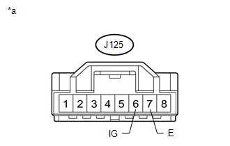
(a) Disconnect the J35 clearance warning ECU assembly connector.

(b) Disconnect the J125 back sonar or clearance sonar switch assembly connector.

(c) Measure the resistance according to the value(s) in the table below.

Standard Resistance:

Tester Connection

Condition

Specified Condition

J35-11 (IG) - J125-3 (ECU)

Always

Below 1 Ω

J35-11 (IG) - Body ground

Always

10 kΩ or higher

J35-16 (E) - Body ground

Always

Below 1 Ω

OK

PROCEED TO NEXT SUSPECTED AREA SHOWN IN PROBLEM SYMPTOMS TABLE

NG

REPAIR OR REPLACE HARNESS OR CONNECTOR

    Clearance Warning Buzzer Circuit

    Front Clearance Sonar Sensor LH Circuit

    See More:

    Toyota Tundra Service Manual > Blind Spot Monitor System: Short to +B in Outer Mirror Indicator(Slave) (C1AB1)
    DESCRIPTION This DTC is stored when the blind spot monitor sensor LH detects a short to +B in the outer rear view mirror indicator LH. DTC No. DTC Detection Condition Trouble Area C1AB1 Both of the following conditions are met: The blind spot monitor system is on The blind spot monitor sensor is not ...

    Toyota Tundra Owners Manual

    Toyota Tundra Service Manual

    © 2025 Copyright www.ttundra.com
    0.013