DESCRIPTION The No. 1 ultrasonic sensor sends and receives ultrasonic waves. Based on the received wave, the sensor calculates the approximate distance value between the vehicle and the obstacle, and sends the distance value as a signal to the clearance warning ECU assembly. WIRING DIAGRAM 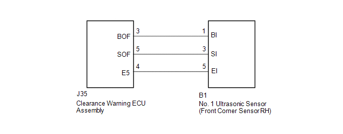 PROCEDURE
(a) Remove the No. 1 ultrasonic sensor (front corner sensor RH) (See page
(b) Inspect the No. 1 ultrasonic sensor (front corner sensor RH) (See page
(a) Disconnect the B1 No. 1 ultrasonic sensor (front corner sensor RH) connector. (b) Disconnect the J35 clearance warning ECU assembly connector. (c) Measure the resistance according to the value(s) in the table below. Standard Resistance:
|
Toyota Tundra Service Manual > Vehicle Stability Control System: System Description
SYSTEM DESCRIPTION FUNCTION DESCRIPTION (a) ABS (Anti-lock Brake System) (1) The ABS helps prevent the wheels from locking when the brakes are applied firmly or when braking on a slippery surface. (b) EBD (Electronic Brake force Distribution) (1) The EBD control utilizes ABS, and performs proper bra ...


