OPERATION CHECK 1. CHECK INITIAL CHECK FUNCTION
(a) Check the initial check function for the sensor.
- Approximately 0.4 seconds after the ignition switch has been turned to
the ON position and the back sonar or clearance sonar switch assembly
has been turned ON, all sensors will be checked by the system.
- When the vehicle has been shifted from P, the system will change to the
obstacle detection operation according to the shift position.
- If there are no changes in the conditions, such as those listed above
(speed or shift position), the sensor check operation will be halted
after approximately 5 seconds have elapsed. If one or more sensors are
anomalous, check operation for all of the sensors will continue (sensors
will continue transmitting).
2. MALFUNCTION DISPLAY (MULTI-INFORMATION DISPLAY) (a) Open circuit indication
(1)
If there is an open circuit between the ultrasonic sensor and the
clearance warning ECU assembly or a sensor is malfunctioning, the
malfunction is displayed as shown in the illustration.
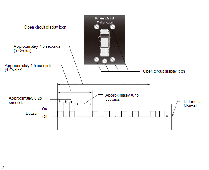
HINT:
- If "Parking Assist Malfunction" is displayed, refer to the Problem Symptoms Table to inspect the problem.
Click here 
- Buzzer sounding is stopped after approximately 7.5 seconds elapsed.
(b) Frozen indication (1)
If a sensor is covered with foreign matter, such as mud or snow, the
affected sensor is displayed as shown in the illustration.
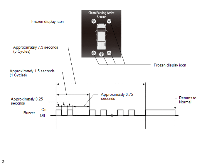
HINT:
- Check if any foreign matter is attached to the ultrasonic sensors and theirsurrounding areas
Click here
- Buzzer sounding is stopped after approximately 7.5 seconds elapsed.
- If "Clean Parking Assist sensor" is displayed, refer to the Problem Symptoms Table to inspect the problem.
Click here
3. DETECTION RANGE MEASUREMENT AND INDICATOR CHECK NOTICE:
Make sure that the vehicle does not move by applying the parking brake firmly.
(a) Turn the ignition switch to ON. (b) Move the shift lever to R to check the front corner sensors, rear corner sensors and back sensors.
(c) Move the shift lever to the D, S and N position to check the front corner sensors.
(d) Turn the back sonar or clearance sonar switch assembly ON. (e) Move a pole around the sensor to measure the detection range of the sensor.
NOTICE:
- These detection ranges are applicable when positioning the pole parallel or perpendicular to the ground.
- The ranges vary depending on the measuring method and type of obstacle (such as walls).
- For close-range, medium-range detection and long-range detection, the
values shown are for when using a pole with a diameter of 60 mm (2.36
in.). For longest-range detection, the values shown are for when using a
pole with a diameter of 400 mm (15.7 in.).
- The detection range of the resin bumper and steel bumper are not the
same, as their installation positions are slightly different.
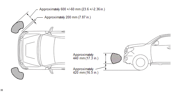
(1) Front corner sensors detection range
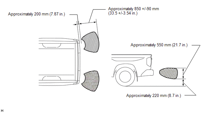
 (2) Rear corner sensors detection range
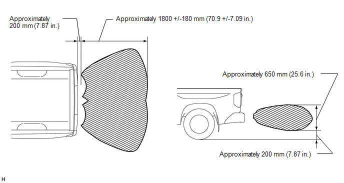
 (3) Rear center sensors detection range
 (f)
When the No. 1 ultrasonic sensors (front corner sensor) have detected
an obstacle, check the multi-information display displays and buzzer
sounds. Operation Condition |
Ignition Switch | Back Sonar or Clearance Sonar Switch Assembly |
Shift Lever Position | Vehicle Speed | |
ON | On |
D, S, N, R | 10 km/h (6.2 mph) or less |
(1) Check the buzzer sounds with the back sonar or clearance sonar switch assembly on.
 Front corner detection range Front corner detection range |
Detection | Distance | |
1. Close-range detection | Within 300 +/-30 mm (11.8 +/-1.18 in.) | |
2. Medium-range detection | 300 +/-30 to 450 +/-50 mm (11.8 +/-1.18 to 17.7 +/-1.97 in.) | |
3. Long-range detection | 450 +/-50 to 600 +/-60 mm (17.7 +/-1.97 to 23.6 +/-2.36 in.) |
HINT: Ultrasonic
waves are used to measure the detection range. However, the detection
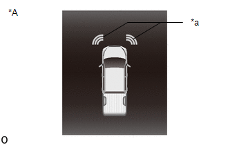
range may vary depending on the ambient temperature. (2) Check the indicator and buzzer on the combination meter assembly when the front corner sensors have detected an obstacle.
|
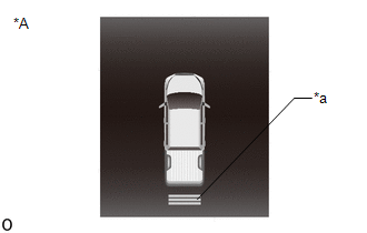
*A | Combination Meter Assembly | |
*a | Front Corner Sensor Display | Combination meter assembly |
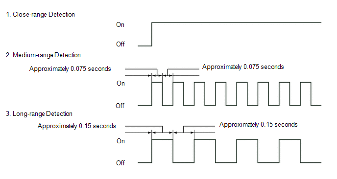
Detection Range | Buzzer |
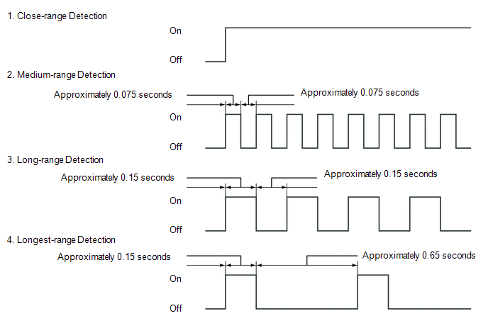
Indicator displayed | | 1. Close-range detection |
Sounds continuously | Corner indicator(s) are blinking | |
2. Medium-range detection | Sounds intermittently
(ON: 0.075 seconds / OFF: 0.075 seconds) |
Corner indicator(s) are illuminated | |
3. Long-range detection | Sounds intermittently
(ON: 0.15 seconds / OFF: 0.15 seconds) |
Corner indicator(s) are illuminated |
HINT: Ultrasonic
waves are used to measure the detection range. However, the detection
range may vary depending on the ambient temperature. (g)
When the No. 2 ultrasonic sensors (rear corner sensor) have detected an
obstacle, check the multi-information display in the combination meter
assembly displays and buzzer in the combination meter assembly sounds
with the back sonar or clearance sonar switch assembly ON. Operation Condition |
Ignition Switch | Back Sonar or Clearance Sonar Switch Assembly |
Shift Lever Position | Vehicle Speed | |
ON | On |
R | No Limit |
(1) Check the buzzer sounds with the back sonar or clearance sonar switch assembly on.
Rear corner detection range |
Detection | Distance | |
1. Close-range detection | Within 400 +/-40 mm (15.7 +/-1.57 in.) | |
2. Medium-range detection | 400 +/-40 to 600 +/-60 mm (15.7 +/-1.57 to 23.6 +/-2.36 in.) | |
3. Long-range detection | 600 +/-60 to 850 +/-90 mm (23.6 +/-2.36 to 33.5 +/-3.54 in.) |
HINT: Ultrasonic
waves are used to measure the detection range. However, the detection
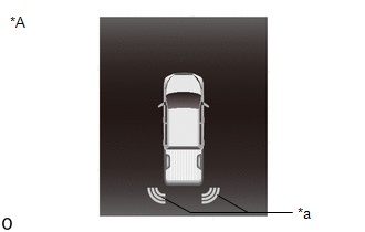
range may vary depending on the ambient temperature. (2) Check the combination meter assembly and buzzer when the rear corner sensors have detected an obstacle.
|
*A | Combination Meter Assembly | |
*a | Rear Corner Sensor Display | Combination meter assembly |
Detection Range | Buzzer |
Indicator displayed | | 1. Close-range detection |
Sounds continuously | Corner indicator(s) are blinking | |
2. Medium-range detection | Sounds intermittently
(ON: 0.075 seconds / OFF: 0.075 seconds) |
Corner indicator(s) are illuminated | |
3. Long-range detection | Sounds intermittently
(ON: 0.15 seconds / OFF: 0.15 seconds) |
Corner indicator(s) are illuminated |
HINT: Ultrasonic
waves are used to measure the detection range. However, the detection
range may vary depending on the ambient temperature. (h)
When the No. 3 ultrasonic sensors (rear center sensor) have detected an
obstacle, check the multi-information display displays and buzzer in
the combination meter assembly sounds with the back sonar or clearance
sonar switch assembly ON. Operation Condition |
Ignition Switch | Back Sonar or Clearance Sonar Switch Assembly |
Shift Lever Position | Vehicle Speed | |
ON | On |
R | No limit |
(1) Check the buzzer sounds with the back sonar or clearance sonar switch assembly on.
 Rear center detection range Rear center detection range |
Detection | Distance | |
1. Close-range detection | Within 500 +/-50 mm (19.7 +/-1.97 in.) | |
2. Medium-range detection | 500 +/-50 to 750 +/-80 mm (19.7 +/-1.97 to 29.5 +/-2.95 in.) | |
3. Long-range detection | 750 +/-80 to 1000 +/-100 mm (29.5 +/-2.95 to 39.4 +/-3.94 in.) | |
4. Longest-range detection | 1000 +/-100 to 1800 +/-180 mm (39.4 +/-3.94 to 70.9 +/-7.09 in.) |
HINT: Ultrasonic
waves are used to measure the detection range. However, the detection
range may vary depending on the ambient temperature. (2) Check the combination meter assembly and buzzer when the rear center sensors have detected an obstacle.
|
*A | Combination Meter Assembly | |
*a | Rear Center Sensor Display | Combination meter assembly |
Detection Range | Buzzer |
Indicator displayed | | 1. Close-range detection |
Sounds continuously | Rear center indicator is blinking | |
2. Medium-range detection | Sounds intermittently
(ON: 0.075 seconds / OFF: 0.075 seconds) |
Rear center indicator is illuminated | |
3. Long-range detection | Sounds intermittently
(ON: 0.15 seconds / OFF: 0.15 seconds) |
Rear center indicator is illuminated | |
4. Longest-range detection |
Sounds intermittently (ON: 0.15 seconds / OFF: 0.65 seconds) |
Rear center indicator is illuminated |
HINT: Ultrasonic
waves are used to measure the detection range. However, the detection
range may vary depending on the ambient temperature. | 

