Toyota Tundra Service Manual: Parts Location

PARTS LOCATION

ILLUSTRATION
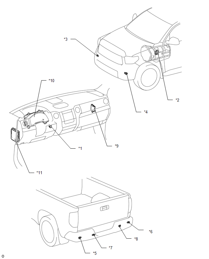
*1

BACK SONAR OR CLEARANCE SONAR SWITCH ASSEMBLY

*2

PARK/NEUTRAL POSITION SWITCH ASSEMBLY

*3

NO. 1 ULTRASONIC SENSOR (FRONT CORNER SENSOR RH)

*4

NO. 1 ULTRASONIC SENSOR (FRONT CORNER SENSOR LH)

*5

NO. 2 ULTRASONIC SENSOR (FRONT CORNER SENSOR LH)

*6

NO. 2 ULTRASONIC SENSOR (REAR CORNER SENSOR RH)

*7

NO. 3 ULTRASONIC SENSOR (REAR CENTER SENSOR LH)

*8

NO. 3 ULTRASONIC SENSOR (REAR CENTER SENSOR RH)

*9

CLEARANCE WARNING ECU ASSEMBLY

*10

COMBINATION METER ASSEMBLY

*11

COWL SIDE JUNCTION BLOCK LH

- ECU-IG1 NO.4 FUSE

- BKUP LP FUSE (for Floor Shift Type)

-

-

    Park / Neutral Position Switch Circuit

    Precaution

    See More:

    Toyota Tundra Service Manual > Sfi System: Diagnostic Trouble Code Chart
    DIAGNOSTIC TROUBLE CODE CHART HINT: Factors such as instrument type may cause readings to differ slightly from the stated values. If any DTCs are displayed during a check mode DTC check, check the circuit for the DTCs listed in the table below. For details of each DTC, refer to the "See page" indica ...

    Toyota Tundra Owners Manual

    Toyota Tundra Service Manual

    © 2025 Copyright www.ttundra.com
    0.0276