DESCRIPTION The No. 2 ultrasonic sensor sends and receives ultrasonic waves. Based on the received wave, the sensor calculates the approximate distance value between the vehicle and the obstacle, and sends the distance value as a signal to the clearance warning ECU assembly. WIRING DIAGRAM 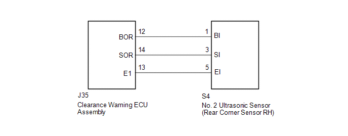 PROCEDURE
(a) Remove the No. 2 ultrasonic sensor (rear corner sensor RH) (See page
(b) Inspect the No. 2 ultrasonic sensor (rear corner sensor RH) (See page
(a) Disconnect the S4 No. 2 ultrasonic sensor (rear corner sensor RH) connector. (b) Disconnect the J35 clearance warning ECU assembly connector. (c) Measure the resistance according to the value(s) in the table below. Standard Resistance:
|
Toyota Tundra Service Manual > Climate Control Seat Switch: Removal
REMOVAL PROCEDURE 1. REMOVE SHIFT LEVER KNOB SUB-ASSEMBLY 2. REMOVE UPPER REAR CONSOLE PANEL SUB-ASSEMBLY 3. REMOVE UPPER CONSOLE PANEL SUB-ASSEMBLY 4. REMOVE REAR CONSOLE END PANEL SUB-ASSEMBLY 5. REMOVE CONSOLE BOX CARPET 6. REMOVE REAR CONSOLE BOX ASSEMBLY 7. REMOVE FRONT CONSOLE BOX 8. REMOVE AI ...

 ).
).


