WIRING DIAGRAM 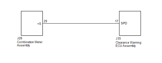 PROCEDURE
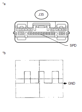
(b) Using an oscilloscope, check the signal waveform of the combination meter assembly. Measurement Condition
OK: Refer to the illustration. HINT: As the vehicle speed increases, the wave length shortens. Text in Illustration
(a) Disconnect the J35 clearance warning ECU assembly connector. (b) Disconnect the J28 combination meter assembly connector. (c) Measure the resistance according to the value(s) in the table below. Standard Resistance:
|
Toyota Tundra Service Manual > Air Conditioning: Magnetic Clutch Relay
On-vehicle Inspection ON-VEHICLE INSPECTION PROCEDURE 1. INSPECT MAGNETIC CLUTCH RELAY (MG CLT) (a) Remove the magnetic clutch relay from the engine room relay block. (b) Measure the resistance according to the value(s) in the table below. Standard Resistance: Tester Connection Condition Specified C ...