Toyota Tundra Service Manual: Image from Camera for Rear View Monitor is Abnormal

DESCRIPTION

This is the display signal circuit between the navigation receiver assembly and the television camera assembly.

WIRING DIAGRAM
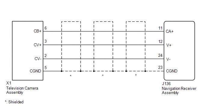
PROCEDURE

1.

CHECK HARNESS AND CONNECTOR (NAVIGATION RECEIVER ASSEMBLY - TELEVISION CAMERA ASSEMBLY)

NG

REPAIR OR REPLACE HARNESS OR CONNECTOR

OK

2.

CHECK NAVIGATION RECEIVER ASSEMBLY

B

REPLACE NAVIGATION RECEIVER ASSEMBLY

C

REPLACE NAVIGATION RECEIVER ASSEMBLY

A

3.

CHECK NAVIGATION RECEIVER ASSEMBLY

B

REPLACE NAVIGATION RECEIVER ASSEMBLY

C

REPLACE NAVIGATION RECEIVER ASSEMBLY

A

4.

CHECK TELEVISION CAMERA ASSEMBLY

OK

PROCEED TO NEXT SUSPECTED AREA SHOWN IN PROBLEM SYMPTOMS TABLE

NG

REPLACE TELEVISION CAMERA ASSEMBLY

    How To Proceed With Troubleshooting

    Parts Location

    See More:

    Toyota Tundra Service Manual > Airbag System: Curtain Shield Airbag Sensor (RH) (B1630,B1635)
    DESCRIPTION The No. 2 side airbag sensor assembly LH or RH consists of a lateral deceleration sensor, etc. If the airbag sensor assembly receives signals from the lateral deceleration sensor, it determines whether the SRS should be activated. DTC B1630 or B1635 is stored when a malfunction is detect ...

    Toyota Tundra Owners Manual

    Toyota Tundra Service Manual

    © 2024 Copyright www.ttundra.com
    0.0099