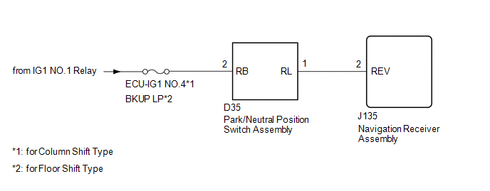
DESCRIPTION The navigation receiver assembly receives a reverse signal from the park/neutral position switch assembly. WIRING DIAGRAM
 CAUTION / NOTICE / HINT
NOTICE: Inspect the fuses for circuits related to this system before performing the following procedure. PROCEDURE
| 1. |
CHECK VEHICLE SIGNAL (OPERATION CHECK) |
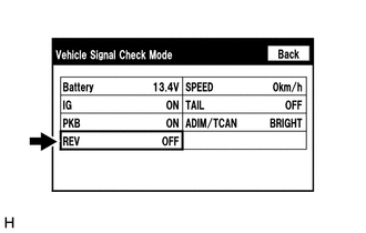
| (a) Enter the "Function Check/Setting I" mode and select "Vehicle Signal" (See page
 ). ). | |
(b) Check that the display changes between ON and OFF according to the shift lever position.
OK: |
Shift Lever Position | Display | |
R | ON | |
Except R | OFF |
HINT: This
display is updated once per second. As a result, it is normal for the
display to lag behind the actual shift lever position.
| OK |
 | PROCEED TO NEXT SUSPECTED AREA SHOWN IN PROBLEM SYMPTOMS TABLE |
|
NG |
 | |
| 2. |
CHECK NAVIGATION RECEIVER ASSEMBLY |
| (a) Disconnect the navigation receiver assembly connector. |
|
(b) Measure the voltage according to the value(s) in the table below. Standard Voltage: |
Tester Connection | Condition |
Specified Condition | |
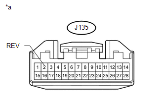
J135-2 (REV) - Body ground | Ignition switch ON, shift lever in R |
7.5 to 14 V | |
J135-2 (REV) - Body ground | Ignition switch ON, shift lever not in R |
Below 1 V | Text in Illustration |
*a | Front view of wire harness connector (to Navigation Receiver Assembly) | Result |
Result | Proceed to | |
OK (for Column Shift Type) |
A | | OK (for Floor Shift Type) |
B | | NG |
C |
| A |
| REPLACE NAVIGATION RECEIVER ASSEMBLY |
| B |
| REPLACE NAVIGATION RECEIVER ASSEMBLY |
|
C | |
| |
| 3. |
CHECK HARNESS AND CONNECTOR (NAVIGATION RECEIVER ASSEMBLY - PARK/NEUTRAL POSITION SWITCH ASSEMBLY) |
(a) Disconnect the J135 navigation receiver assembly connector. (b) Disconnect the D35 park/neutral position switch assembly connector.
(c) Measure the resistance according to the value(s) in the table below.
Standard Resistance: |
Tester Connection | Condition |
Specified Condition | |
J135-2 (REV) - D35-1 (RL) |
Always | Below 1 Ω | |
J135-2 (REV) - Body ground |
Always | 10 kΩ or higher |
| NG |
| REPAIR OR REPLACE HARNESS OR CONNECTOR |
|
OK | |
| |
| 4. |
CHECK HARNESS AND CONNECTOR (PARK/NEUTRAL POSITION SWITCH ASSEMBLY - BATTERY) |
| (a) Disconnect the park/neutral position switch assembly connector. |
|
(b) Measure the voltage according to the value(s) in the table below. Standard Voltage: |
Tester Connection | Switch Condition |
Specified Condition | |
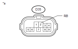
D35-2 (RB) - Body ground |
Ignition switch ON | 11 to 14 V | Text in Illustration |
*a | Front view of wire harness connector (to Park/Neutral Position Switch Assembly) |
HINT: *: Replace park/neutral position switch assembly procedure
- for A760E:
- for A760F:
- for AB60E:
- for AB60F:
| OK |
| REPLACE PARK/NEUTRAL POSITION SWITCH ASSEMBLY* |
| NG |
| REPAIR OR REPLACE HARNESS OR CONNECTOR | |