TERMINALS OF ECU 1. CHECK NAVIGATION RECEIVER ASSEMBLY 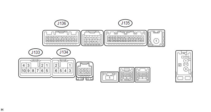 (a) Disconnect the J133 and J135 navigation receiver assembly connectors. (b) Measure the voltage and resistance according to the value(s) in the table below.
(c) Reconnect the J133 and J135 navigation receiver assembly connectors. (d) Measure the voltage and waveform according to the value(s) in the table below.
(e) Using an oscilloscope, check the waveform. 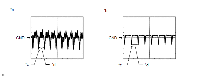
(1) Waveform 1 Measurement Condition
HINT: The video waveform changes according to the image sent by the television camera assembly. (2) Waveform 2 Measurement Condition
HINT: The video waveform changes according to the image sent by the television camera assembly. |
Toyota Tundra Owners Manual > Operating the lights and
wipers: Headlight switch
The headlights can be operated manually or automatically. Operating instructions Operating the switch turns on the lights as follows: For U.S.A. The headlights, daytime running lights and all the lights listed above turn on and off automatically. (When the engine switch is in the "ON" position.) &n ...


