Toyota Tundra Service Manual: Image from Camera for Rear View Monitor is Abnormal

DESCRIPTION

This is the display signal circuit between the radio and display receiver assembly and the television camera assembly.

WIRING DIAGRAM
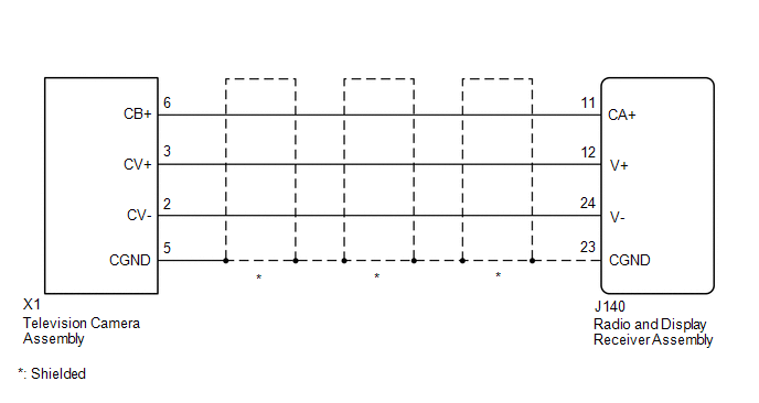
PROCEDURE

1.

CHECK HARNESS AND CONNECTOR (RADIO AND DISPLAY RECEIVER ASSEMBLY - TELEVISION CAMERA ASSEMBLY)

NG

REPAIR OR REPLACE HARNESS OR CONNECTOR

OK

2.

CHECK RADIO AND DISPLAY RECEIVER ASSEMBLY

B

REPLACE RADIO AND DISPLAY RECEIVER ASSEMBLY

C

REPLACE RADIO AND DISPLAY RECEIVER ASSEMBLY

A

3.

CHECK RADIO AND DISPLAY RECEIVER ASSEMBLY

B

REPLACE RADIO AND DISPLAY RECEIVER ASSEMBLY

C

REPLACE RADIO AND DISPLAY RECEIVER ASSEMBLY

A

4.

CHECK TELEVISION CAMERA ASSEMBLY

OK

PROCEED TO NEXT SUSPECTED AREA SHOWN IN PROBLEM SYMPTOMS TABLE

NG

REPLACE TELEVISION CAMERA ASSEMBLY

    How To Proceed With Troubleshooting

    Parts Location

    See More:

    Toyota Tundra Service Manual > Roof Drip Side Finish Moulding: Installation
    INSTALLATION CAUTION / NOTICE / HINT HINT: Use the same procedures for the RH side and LH side. The procedures listed below are for the LH side. When installing a clip, heat the vehicle body and clip using a heat light. When installing the moulding, heat the vehicle body and moulding using a heat li ...

    Toyota Tundra Owners Manual

    Toyota Tundra Service Manual

    © 2024 Copyright www.ttundra.com
    0.0324