TERMINALS OF ECU 1. CHECK RADIO AND DISPLAY RECEIVER ASSEMBLY
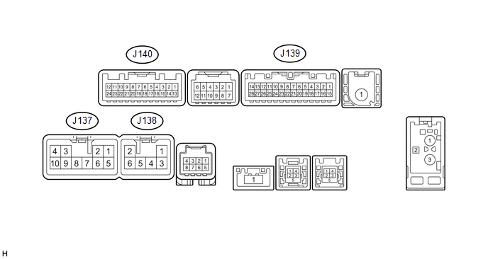 (a) Disconnect the J137 and J139 radio and display receiver assembly connectors.
(b) Measure the voltage and resistance according to the value(s) in the table below. |
Terminal No. (Symbol) | Wiring Color |
Terminal Description | Condition |
Specification | |
J137-3 (ACC1) - J137-7 (GND1) |
GR - BR | Power source (ACC) |
Ignition switch off | Below 1 V | |
Ignition switch ACC | 11 to 14 V | |
J137-4 (+B1) - J137-7 (GND1) |
LA-SB - BR | Power source (+B) |
Always | 11 to 14 V | |
J137-7 (GND1) - Body ground |
BR - Body ground | Ground |
Always | Below 1 Ω | |
J139-1 (IG) - J137-7 (GND1) |
BE - BR | Power source (IG) |
Ignition switch off | Below 1 V | |
Ignition switch ON | 11 to 14 V |
(c) Reconnect the J137 and J139 radio and display receiver assembly connectors.
(d) Measure the voltage and waveform according to the value(s) in the table below. |
Terminal No. (Symbol) | Wiring Color |
Terminal Description | Condition |
Specification | |
J139-2 (REV) - J137-7 (GND1) |
Y - BR | Reverse signal |
Ignition switch ON, shift lever in R |
7.5 to 14 V | | Ignition switch ON, shift lever not in R |
Below 1 V | |
J140-11 (CA+) - J140-23 (CGND) |
B - Shielded | Power source |
Ignition switch ACC | 5.5 to 7.05 V | |
J140-12 (V+) - J140-24 (V-) |
R - W | Display signal |
Ignition switch ON | Pulse generation (See waveform 1) | |
Ignition switch ON, screen blacked out by covering camera lens |
Pulse generation (See waveform 2) | |
J140-23 (CGND) - Body ground |
Shielded - Body ground |
Shielded ground | Always |
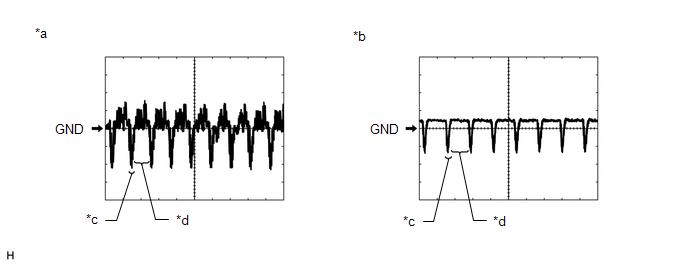
Below 1 Ω | (e) Using an oscilloscope, check the waveform.
|
*a | Waveform 1 |
*b | Waveform 2 | |
*c | Synchronization Signal |
*d | Video Waveform |
(1) Waveform 1 Measurement Condition |
Item | Content | |
Terminal No. (Symbol) |
J140-12 (V+) - J140-24 (V-) | |
Tool Setting | 0.2 V/DIV., 50 μs/DIV. | |
Condition | Ignition switch ON |
HINT: The video waveform changes according to the image sent by the television camera assembly.
(2) Waveform 2 Measurement Condition |
Item | Content | |
Terminal No. (Symbol) |
J140-12 (V+) - J140-24 (V-) | |
Tool Setting | 0.2 V/DIV., 50 μs/DIV. | |
Condition | Ignition switch ON, screen blacked out by covering camera lens |
HINT: The video waveform changes according to the image sent by the television camera assembly. | 

