Components COMPONENTS ILLUSTRATION 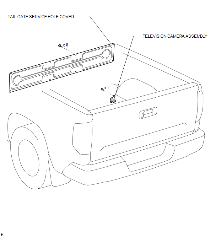 Installation INSTALLATION CAUTION / NOTICE / HINT HINT: A bolt without a torque specification is shown in the standard bolt chart (see page
PROCEDURE 1. INSTALL TELEVISION CAMERA ASSEMBLY (a) Install the television camera assembly with the 2 bolts. (b) Connect the television camera connector. 2. INSTALL TAIL GATE SERVICE HOLE COVER
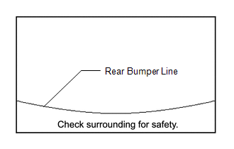
3. CHECK TELEVISION CAMERA ASSEMBLY ANGLE
Removal REMOVAL PROCEDURE 1. REMOVE TAIL GATE SERVICE HOLE COVER
2. REMOVE TELEVISION CAMERA ASSEMBLY 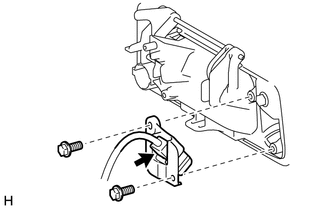 (a) Disconnect the television camera connector. (b) Remove the 2 bolts and television camera assembly. |
Toyota Tundra Service Manual > Vehicle Stability Control System: Performance Decline of Brake Function (C1441)
DESCRIPTION The skid control ECU judges brake failure conditions have occurred based on signals from the brake pedal load sensing switch and master cylinder pressure sensor. NOTICE: Do not intentionally stop the engine when driving. Even when no malfunction has occurred in the brake system, DTC C144 ...

 ).
).