Toyota Tundra Service Manual: Components

COMPONENTS

ILLUSTRATION
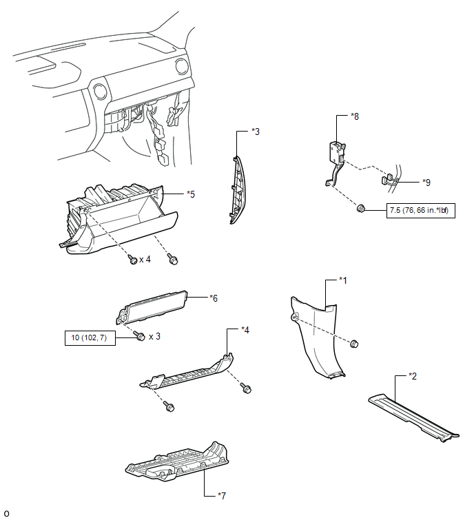
*1

COWL SIDE TRIM BOARD RH

*2

FRONT DOOR SCUFF PLATE RH

*3

INSTRUMENT SIDE PANEL RH

*4

LOWER INSTRUMENT PANEL

*5

LOWER INSTRUMENT PANEL FINISH PANEL SUB-ASSEMBLY RH

*6

LOWER NO. 2 INSTRUMENT PANEL AIRBAG ASSEMBLY

*7

NO. 2 INSTRUMENT PANEL UNDER COVER SUB-ASSEMBLY

*8

TRAILER BRAKE CONTROL ECU (BRAKE CONTROL WITH BRACKET RELAY)

*9

CONNECTOR

-

-

N*m (kgf*cm, ft.*lbf): Specified torque

-

-

    Trailer Brake Control Ecu

    Installation

    See More:

    Toyota Tundra Service Manual > Lighting System: Hazard Warning Switch Circuit
    DESCRIPTION The combination meter assembly receives the air conditioning control assembly (hazard warning signal switch) ON signal and controls the operation of the hazard warning lights. WIRING DIAGRAM CAUTION / NOTICE / HINT NOTICE: When replacing the combination meter assembly, always replace it ...

    Toyota Tundra Owners Manual

    Toyota Tundra Service Manual

    © 2026 Copyright www.ttundra.com
    0.032