PARTS LOCATION ILLUSTRATION 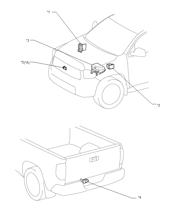
ILLUSTRATION 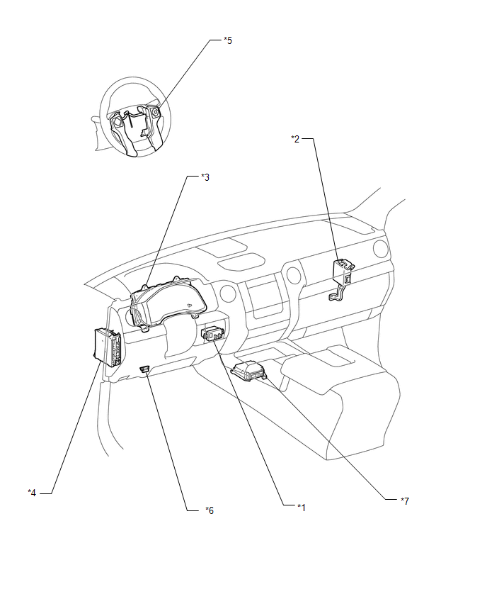
|
Toyota Tundra Service Manual > Rear Leaf Spring: Installation
INSTALLATION CAUTION / NOTICE / HINT HINT: Use the same procedures for the RH side and LH side. The procedures listed below are for the LH side. A bolt without a torque specification is shown in the standard bolt chart (see page ). PROCEDURE 1. INSTALL REAR SPRING SHACKLE BUSH (a) Install the 2 shac ...


