|
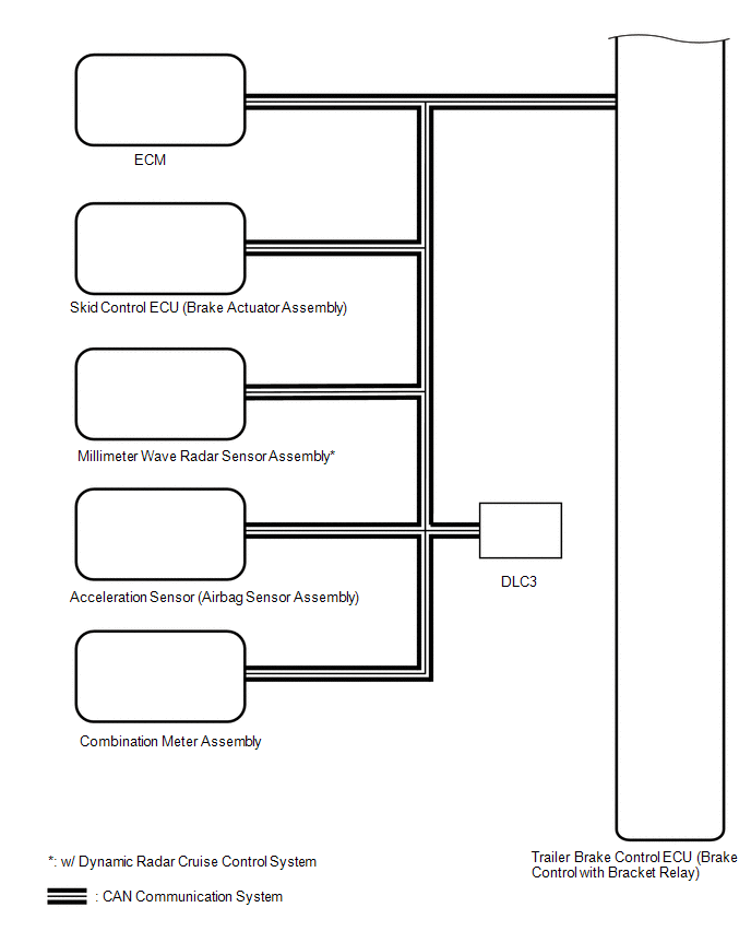
Sender | Receiver |
Signal | Line |
|
Skid Control ECU (Brake Actuator Assembly) |
Trailer Brake Control ECU (Brake Control with Bracket Relay) |
- Vehicle speed signal
- Master cylinder pressure signal
- Anti-lock brake control status signal
- Hill-start assist control status signal
- Trailer sway control status signal
| CAN |
|
ECM | Trailer Brake Control ECU (Brake Control with Bracket Relay) |
Dynamic radar cruise control system brake request signal* |
CAN |
| Acceleration Sensor (Airbag Sensor Assembly) |
Trailer Brake Control ECU (Brake Control with Bracket Relay) |
Vehicle acceleration/deceleration information signal |
CAN |
| Millimeter Wave Radar Sensor Assembly |
Trailer Brake Control ECU (Brake Control with Bracket Relay) |
Pre-collision system deceleration request signal |
CAN |
| Trailer Brake Control ECU (Brake Control with Bracket Relay) |
Combination Meter Assembly |
- Trailer connection status signal
- Trailer type signal
- Gain setting signal
- Output percentage of trailer brake signal
| CAN |
 Communication Table

