Toyota Tundra Service Manual: Terminals Of Ecu

TERMINALS OF ECU

1. CHECK TRAILER BRAKE CONTROL ECU (BRAKE CONTROL WITH BRACKET RELAY)

(a) Disconnect the J172 trailer brake control ECU (brake control with bracket relay) connector and measure the voltage or resistance on the wire harness side.

Text in Illustration

*a

Front view of wire harness connector

(to Trailer Brake Control ECU [Brake Control with Bracket Relay])

-

-

Terminal No. (Symbol)

Wiring Color

Terminal Description

Condition

Specified Condition

J172-2 (+B) - J172-20 (GND)

B - W-B

Power supply (from battery)

Always

11 to 14 V

J172-5 (CANH) - J172-14 (CANL)

B - W

CAN communication line

Ignition switch off

54 to 69 Ω

J172-13 (IG) - J172-20 (GND)

V - W-B

IG power source

Ignition switch ON

11 to 14 V

J172-20 (GND) - Body ground

W-B - Body ground

Trailer brake control ECU (brake control with bracket relay) ground

Always

Below 1 Ω

(b) Connect the J172 trailer brake control ECU (brake control with bracket relay) connector.

(c) Measure the voltage and resistance according to the value(s) in the table below. If the result is not as specified, the ECU may be malfunctioning.
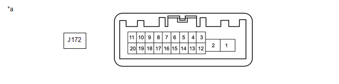
Text in Illustration

*a

Component without harness connected

(Trailer Brake Control ECU [Brake Control with Bracket Relay])

-

-

HINT:

Measure the values on the wire harness side while the connector is connected.

Terminal No. (Symbol)

Wiring Color

Terminal Description

Condition

Specified Condition

J172-1 (BRK) - J172-20 (GND)

L - W-B

Trailer brake output

  • Ignition switch ON
  • No trailer brake control

Below 3.5 V

  • Ignition switch ON
  • Manual trailer brake output slider operated to maximum position (100%)

11 to 14 V

J172-6 (GA-) - J172-20 (GND)

BR - W-B

GAIN (-) selection button input

  • Ignition switch ON
  • GAIN (-) selection button OFF

11 to 14 V

  • Ignition switch ON
  • GAIN (-) selection button ON

Below 1 V

J172-7 (SRW2) - J172-20 (GND)

Y - W-B

Manual trailer brake output slider adjustable resistor 2 input

  • Ignition switch ON
  • No trailer brake control

4.5 to 5.5 V

  • Ignition switch ON
  • Manual trailer brake output slider operated to maximum position (100%)

0 to 1.0 V

J172-9 (SRW1) - J172-20 (GND)

R - W-B

Manual trailer brake output slider adjustable resistor 1 input

  • Ignition switch ON
  • No trailer brake control

0 to 1.0 V

  • Ignition switch ON
  • Manual trailer brake output slider operated to maximum position (100%)

4.5 to 5.5 V

J172-11 (SRRT) - J172-20 (GND)

G - W-B

Manual trailer brake output slider GND terminal

Ignition switch ON

0 to 0.5 V

J172-15 (GA+) - J172-20 (GND)

R - W-B

GAIN (+) selection button input

  • Ignition switch ON
  • GAIN (+) selection button OFF

11 to 14 V

  • Ignition switch ON
  • GAIN (+) selection button ON

Below 1 V

J172-16 (SRF)- J172-20 (GND)

P - W-B

Manual trailer brake output slider power supply output

Ignition switch ON

4.0 to 6.43 V

J172-18 (SRR) - J172-20 (GND)

L - W-B

Manual trailer brake output slider upstream power supply reference power supply monitor

Ignition switch ON

4.0 to 6.43 V

    System Diagram

    Control Module Communication Bus "A" Off (U0073,U0123,U0129,U0155)

    See More:

    Toyota Tundra Service Manual > Headlight Assembly(for Led Headlight): Removal
    REMOVAL CAUTION / NOTICE / HINT HINT: Use the same procedure for the RH and LH sides. The procedure listed below is for the LH side. PROCEDURE 1. REMOVE RADIATOR GRILLE SUB-ASSEMBLY 2. REMOVE FRONT END PANEL LH 3. REMOVE HEADLIGHT ASSEMBLY LH (a) Apply protective tape around the headlight assembly L ...

    Toyota Tundra Owners Manual

    Toyota Tundra Service Manual

    © 2024 Copyright www.ttundra.com
    0.0326