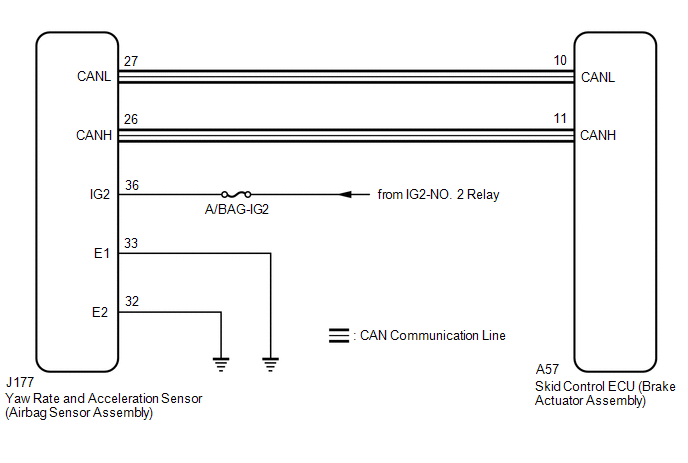
DESCRIPTION The skid
control ECU (brake actuator assembly) receives signals from the yaw rate
and acceleration sensor (airbag sensor assembly) via CAN communication. HINT:
If
there is a malfunction in the bus lines between the yaw rate and
acceleration sensor (airbag sensor assembly) and the CAN communication
system, DTC U0123 (Lost Communication with Yaw Rate Sensor Module) is
output. When U0123 is output together with C1234, C1472 and/or C1474,
inspect and repair the trouble areas indicated by U0123 first. These DTCs may be stored if one of the following occurs:
- Yaw rate and acceleration sensor circuit malfunction.
- Yaw rate and acceleration sensor (airbag sensor assembly) installation abnormality.
- Yaw rate and acceleration sensor signal malfunction.
|
DTC No. | Detection Item |
DTC Detection Condition | Trouble Area | |
C1234 | Yaw Rate Sensor |
Any of the following is detected:
- The yaw rate sensor value is less than -30.0 deg/s or more than 30.0 deg/s for 0.5 seconds or more.
- The yaw rate sensor value is continuously -8.25 deg/s or less or 8.25
deg/s or more for 2 seconds or more with the vehicle stopped and the
engine off, and then the engine is started and the vehicle is driven at 5
km/h (3.1 mph) or more.
- The difference between the input yaw rate sensor value and the yaw rate
sensor value maintained while idling is 14.0 deg/s or more when the
engine is started, and then the vehicle is driven at 5 km/h (3.1 mph) or
more.
|
- Yaw rate sensor (airbag sensor assembly) installation
- Yaw rate sensor (airbag sensor assembly)
- Yaw rate sensor circuit
| | C1472 |
Acceleration Sensor | Any of the following is detected:
- With the vehicle stopped, the internal acceleration value is less than -7 m/s2 or more than 7 m/s2 for 0.1 seconds or more.
- The acceleration sensor offset value calculated by offset calibration
performed while the vehicle is driven is continuously -1.7 m/s2 or less
or 1.7 m/s2 or more for 0.01 seconds.
|
- Acceleration sensor (airbag sensor assembly) installation
- Acceleration sensor (airbag sensor assembly)
- Acceleration sensor circuit
| | C1474 |
Forward and Rearward G Sensor |
The
acceleration sensor offset value calculated by offset calibration
performed while the vehicle is driven is continuously -1.9 m/s2 or less
or 1.9 m/s2 or more for 0.01 seconds. |
- Acceleration sensor (airbag sensor assembly) installation
- Acceleration sensor (airbag sensor assembly)
- Acceleration sensor circuit
| WIRING DIAGRAM
 CAUTION / NOTICE / HINT
NOTICE:
- Inspect the fuses for circuits related to this system before performing the following procedure.
- After replacing or reinstalling the yaw rate and acceleration sensor
(airbag sensor assembly), perform system variant learning and
acceleration sensor zero point calibration.
Click here 
PROCEDURE (a) Check that no CAN communication system DTCs are output.
Click here
|
Result | Proceed to | |
CAN communication system DTCs are not output. |
A | | CAN communication system DTCs are output. |
B |
| B |
 | INSPECT CAN COMMUNICATION SYSTEM |
|
A |
 | |
| 2. |
READ VALUE USING TECHSTREAM (YAW RATE AND ACCELERATION SENSOR) |
(a) Connect the Techstream to the DLC3. (b) Turn the ignition switch to ON.
(c) Enter the following menus: Chassis / ABS/VSC/TRAC / Data List. ABS/VSC/TRAC |
Tester Display | Measurement Item |
Range | Normal Condition |
Diagnostic Note | |
Deceleration Sensor | Lateral acceleration sensor (GL1) reading |
Min.: -18.525 m/s2, Max.: 18.387 m/s2 |
- | During deceleration/acceleration: Changes continuously | |
Deceleration Sensor2 | Longitudinal acceleration sensor (GL2) reading |
Min.: -18.525 m/s2, Max.: 18.387 m/s2 |
- | During deceleration/acceleration: Changes continuously | |
Yaw Rate Sensor | Yaw rate sensor |
Min.: -128°/s, Max.: 127°/s |
Vehicle stopped: 0°/s Turning right: -128 to 0°/s Turning left: 0 to 127°/s |
- | | Forward and Rearward G |
Forward and rearward G |
Min.: -25.10 m/s2, Max.: 24.90 m/s2 |
- | During acceleration/deceleration: Changes in proportion with acceleration |
(d) Check the yaw rate and acceleration sensor (airbag sensor assembly) output value displayed on the Techstream.
|
Result | Proceed to | |
NG (Yaw Rate Sensor output value is stable and does not change when turning) |
A | | NG (Deceleration Sensor and Deceleration Sensor2 output values do not continuously change during deceleration or acceleration) | |
NG
(Forward and Rearward G output value does not change in proportion with
generated acceleration during acceleration/deceleration) | |
OK | B |
| B |
| USE SIMULATION METHOD TO CHECK |
|
A | |
| |
| 3. |
CHECK AIRBAG SENSOR ASSEMBLY INSTALLATION |
(a) Turn the ignition switch off. (b) Check that the yaw rate and acceleration sensor (airbag sensor assembly) has been installed properly.
for Column Shift Type: Click here for Floor Shift Type: Click here
OK: The yaw rate and acceleration sensor (airbag sensor assembly) is tightened to the specified torque.
The yaw rate and acceleration sensor (airbag sensor assembly) is not installed in a tilted position.
| OK |
| REPLACE AIRBAG SENSOR ASSEMBLY |
| NG |
| INSTALL AIRBAG SENSOR ASSEMBLY CORRECTLY | | 

