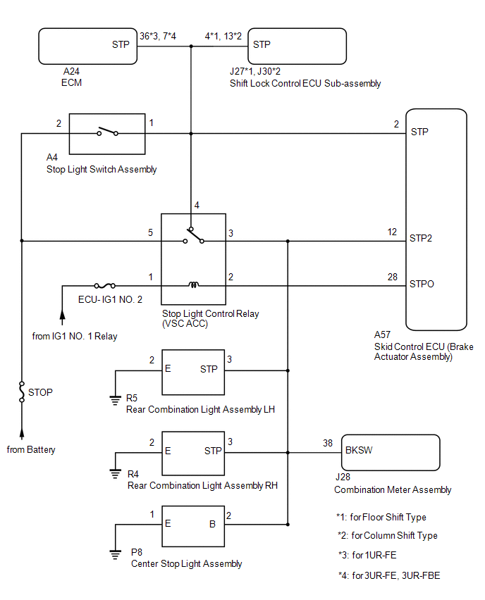
DESCRIPTION The skid
control ECU (brake actuator assembly) receives stop light switch signals
and uses them to determine whether or not the brakes are applied. |
DTC No. | Detection Item |
DTC Detection Condition | Trouble Area | |
C1249 | Open in Stop Light Switch Circuit |
Vehicle driven at 20 km/h (12 mph) or more for 6 minutes or more with stop light switch signal on. |
- Wire harness or connector
- Stop light switch assembly
- Skid control ECU (brake actuator assembly)
- ECM
- Shift lock control ECU sub-assembly
- Combination meter assembly
- Towing brake control
- Rear combination light assembly LH
- Rear combination light assembly RH
- Center stop light assembly
| WIRING DIAGRAM
 CAUTION / NOTICE / HINT
NOTICE:
- When replacing the skid control ECU (brake actuator assembly), perform
system variant learning and acceleration sensor zero point calibration.
Click here 
- Inspect the fuses for circuits related to this system before performing the following procedure.
PROCEDURE |
1. | CHECK BRAKE PEDAL AND STOP LIGHT SWITCH INSTALLATION |
(a) Check the brake pedal height installation Click here
(b) Check the stop light switch assembly installation.
Click here OK: The brake pedal height and stop light switch assembly installation are normal.
| NG |
 | ADJUST BRAKE PEDAL OR STOP LIGHT SWITCH ASSEMBLY |
|
OK |
 | |
| 2. |
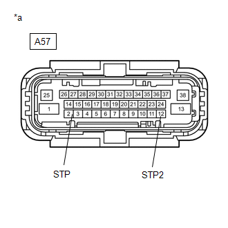
CHECK HARNESS AND CONNECTOR (STP2 AND STP TERMINAL) |
| (a) Turn the ignition switch off. |
 |
|
*a | Front view of wire harness connector
(to Skid Control ECU (Brake Actuator Assembly)) | | |
(b) Make sure that there is no looseness at the locking part and the connecting part of the connector.
OK: The connector is securely connected. (c) Disconnect the A57 skid control ECU (brake actuator assembly) connector.
(d) Check both the connector case and the terminals for deformation and corrosion.
OK: No deformation or corrosion. (e) Measure the voltage according to the value(s) in the table below.
Standard Voltage: |
Tester Connection | Condition |
Specified Condition | |
A57-2 (STP) - Body ground |
Stop light switch assembly on (Brake pedal depressed) |
8 to 14 V | |
A57-2 (STP) - Body ground |
Stop light switch assembly off (Brake pedal released) |
Below 1.5 V | |
A57-12 (STP2) - Body ground |
Stop light switch assembly on (Brake pedal depressed) |
8 to 14 V | |
A57-12 (STP2) - Body ground |
Stop light switch assembly off (Brake pedal released) |
Below 1.5 V |
| NG |
| GO TO STEP 4 |
|
OK | |
| |
(a) Reconnect the A57 skid control ECU (brake actuator assembly) connector.
(b) Clear the DTCs. Click here
(c) Turn the ignition switch off. (d) Start the engine. (e) Drive the vehicle and depress the brake pedal several times to test the stop light circuit.
(f) Check if the same DTC is output. Click here
|
Result | Proceed to | |
C1249 is not output | A | |
C1249 is output | B |
| A |
| USE SIMULATION METHOD TO CHECK |
| B |
| REPLACE BRAKE ACTUATOR ASSEMBLY |
| 4. |
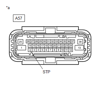
CHECK HARNESS AND CONNECTOR (STP TERMINAL) |
| (a) Turn the ignition switch off. |
 |
|
*a | Front view of wire harness connector
(to Skid Control ECU (Brake Actuator Assembly)) | | |
(b) Make sure that there is no looseness at the locking part and the connecting part of the connector.
OK: The connector is securely connected. (c) Disconnect the A57 skid control ECU (brake actuator assembly) connector.
(d) Remove the stop light control relay (VSC ACC) from the engine room relay block and junction block assembly.
(e) Check both the connector case and the terminals for deformation and corrosion.
OK: No deformation or corrosion. (f) Measure the voltage according to the value(s) in the table below.
Standard Voltage: |
Tester Connection | Condition |
Specified Condition | |
A57-2 (STP) - Body ground |
Stop light switch assembly on (Brake pedal depressed) |
8 to 14 V | |
A57-2 (STP) - Body ground |
Stop light switch assembly off (Brake pedal released) |
Below 1.5 V |
| NG |
| GO TO STEP 10 |
|
OK | |
| |
| 5. |
INSPECT STOP LIGHT CONTROL RELAY (VSC ACC) |
(a) Inspect the stop light control relay (VSC ACC). Click here
OK: The stop light control relay (VSC ACC) is normal.
| NG |
| REPLACE STOP LIGHT CONTROL RELAY (VSC ACC) |
|
OK | |
| |
| 6. |
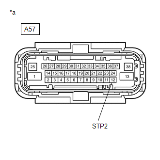
CHECK HARNESS AND CONNECTOR (BRAKE ACTUATOR ASSEMBLY - REAR COMBINATION LIGHT ASSEMBLY LH) |
(a) Install the stop light control relay (VSC ACC) to the engine room relay block and junction block assembly.
| (b) Make sure that there is no looseness at the locking part and the connecting part of the connector.
OK: The connector is securely connected. |
 |
|
*a | Front view of wire harness connector
(to Skid Control ECU (Brake Actuator Assembly)) | | |
(c) Disconnect the R5 rear combination light assembly LH connector. (d) Check both the connector case and the terminals for deformation and corrosion.
OK: No deformation or corrosion. (e) Measure the voltage according to the value(s) in the table below.
Standard Voltage: |
Tester Connection | Condition |
Specified Condition | |
A57-12 (STP2) - Body ground |
Stop light switch assembly on (Brake pedal depressed) |
8 to 14 V | |
A57-12 (STP2) - Body ground |
Stop light switch assembly off (Brake pedal released) |
Below 1.5 V |
| OK |
| REPLACE REAR COMBINATION LIGHT ASSEMBLY LH |
|
NG | |
| |
| 7. |
CHECK HARNESS AND CONNECTOR (BRAKE ACTUATOR ASSEMBLY - REAR COMBINATION LIGHT ASSEMBLY RH) |
| (a) Make sure that there is no looseness at the locking part and the connecting part of the connector.
OK: The connector is securely connected. |
 |
|
*a | Front view of wire harness connector
(to Skid Control ECU (Brake ActuatorAssembly)) | | |
(b) Disconnect the R4 rear combination light assembly RH connector. (c) Check both the connector case and the terminals for deformation and corrosion.
OK: No deformation or corrosion. (d) Measure the voltage according to the value(s) in the table below.
Standard Voltage: |
Tester Connection | Condition |
Specified Condition | |
A57-12 (STP2) - Body ground |
Stop light switch assembly on (Brake pedal depressed) |
8 to 14 V | |
A57-12 (STP2) - Body ground |
Stop light switch assembly off (Brake pedal released) |
Below 1.5 V |
| OK |
| REPLACE REAR COMBINATION LIGHT ASSEMBLY RH |
|
NG | |
| |
| 8. |
CHECK HARNESS AND CONNECTOR (BRAKE ACTUATOR ASSEMBLY - CENTER STOP LIGHT ASSEMBLY) |
| (a) Make sure that there is no looseness at the locking part and the connecting part of the connector.
OK: The connector is securely connected. |
 |
|
*a | Front view of wire harness connector
(to Skid Control ECU (Brake Actuator Assembly)) | | |
(b) Disconnect the P8 center stop light assembly connector. (c) Check both the connector case and the terminals for deformation and corrosion.
OK: No deformation or corrosion. (d) Measure the voltage according to the value(s) in the table below.
Standard Voltage: |
Tester Connection | Condition |
Specified Condition | |
A57-12 (STP2) - Body ground |
Stop light switch assembly on (Brake pedal depressed) |
8 to 14 V | |
A57-12 (STP2) - Body ground |
Stop light switch assembly off (Brake pedal released) |
Below 1.5 V |
| OK |
| REPLACE CENTER STOP LIGHT ASSEMBLY |
|
NG | |
| |
| 9. |
CHECK HARNESS AND CONNECTOR (BRAKE ACTUATOR ASSEMBLY - COMBINATION METER ASSEMBLY) |
| (a) Make sure that there is no looseness at the locking part and the connecting part of the connector.
OK: The connector is securely connected. |
 |
|
*a | Front view of wire harness connector
(to Skid Control ECU (Brake Actuator Assembly)) | | |
(b) Disconnect the J28 combination meter assembly connector. (c) Check both the connector case and the terminals for deformation and corrosion.
OK: No deformation or corrosion. (d) Measure the voltage according to the value(s) in the table below.
Standard Voltage: |
Tester Connection | Condition |
Specified Condition | |
A57-12 (STP2) - Body ground |
Stop light switch assembly on (Brake pedal depressed) |
8 to 14 V | |
A57-12 (STP2) - Body ground |
Stop light switch assembly off (Brake pedal released) |
Below 1.5 V |
| OK |
| REPLACE COMBINATION METER ASSEMBLY |
| NG |
| REPAIR OR REPLACE HARNESS OR CONNECTOR |
| 10. |
CHECK HARNESS AND CONNECTOR (BRAKE ACTUATOR ASSEMBLY - ECM) |
| (a) Make sure that there is no looseness at the locking part and the connecting part of the connector.
OK: The connector is securely connected. |
 |
|
*a | Front view of wire harness connector
(to Skid Control ECU (Brake Actuator Assembly)) | | |
(b) Disconnect the A24 ECM connector. (c) Check both the connector case and the terminals for deformation and corrosion.
OK: No deformation or corrosion. (d) Measure the voltage according to the value(s) in the table below.
Standard Voltage: |
Tester Connection | Condition |
Specified Condition | |
A57-2 (STP) - Body ground |
Stop light switch assembly on (Brake pedal depressed) |
8 to 14 V | |
A57-2 (STP) - Body ground |
Stop light switch assembly off (Brake pedal released) |
Below 1.5 V |
| OK |
| REPLACE ECM |
|
NG | |
| |
| 11. |
CHECK HARNESS AND CONNECTOR (BRAKE ACTUATOR ASSEMBLY - SHIFT LOCK CONTROL ECU SUB-ASSEMBLY) |
| (a) Make sure that there is no looseness at the locking part and the connecting part of the connector.
OK: The connector is securely connected. | |
|
|
*a | Front view of wire harness connector
(to Skid Control ECU (Brake Actuator Assembly)) | | |
(b) for Floor Shift Type: Disconnect the J27 shift lock control ECU sub-assembly connector.
for Column shift Type Disconnect the J30 shift lock control ECU sub-assembly connector.
(c) Check both the connector case and the terminals for deformation and corrosion.
OK: No deformation or corrosion. (d) Measure the voltage according to the value(s) in the table below.
Standard Voltage: |
Tester Connection | Condition |
Specified Condition | |
A57-2 (STP) - Body ground |
Stop light switch assembly on (Brake pedal depressed) |
8 to 14 V | |
A57-2 (STP) - Body ground |
Stop light switch assembly off (Brake pedal released) |
Below 1.5 V |
| OK |
| REPLACE SHIFT LOCK CONTROL ECU SUB-ASSEMBLY |
|
NG | |
| |
| 12. |
CHECK HARNESS AND CONNECTOR (BRAKE ACTUATOR ASSEMBLY - STOP LIGHT SWITCH ASSEMBLY) |
| (a) Make sure that there is no looseness at the locking part and the connecting part of the connector.
OK: The connector is securely connected. | |
|
|
*a | Front view of wire harness connector
(to Skid Control ECU (Brake Actuator Assembly)) | | |
(b) Disconnect the A4 stop light switch assembly connector. (c) Check both the connector case and the terminals for deformation and corrosion.
OK: No deformation or corrosion. (d) Measure the voltage according to the value(s) in the table below.
Standard Voltage: |
Tester Connection | Condition |
Specified Condition | |
A57-2 (STP) - Body ground |
Always | Below 1.5 V |
| OK |
| REPLACE STOP LIGHT SWITCH ASSEMBLY |
| NG |
| REPAIR OR REPLACE HARNESS OR CONNECTOR | | 

