Toyota Tundra Service Manual: Steering Angle Sensor Power Source Voltage Malfunction (C1432)

Toyota Tundra Service Manual / Brake / Brake Control / Dynamic Control Systems / Vehicle Stability Control System / Steering Angle Sensor Power Source Voltage Malfunction (C1432)

DESCRIPTION

This DTC is stored when the skid control ECU (brake actuator assembly) receives a +B line open signal from the steering angle sensor (spiral with sensor cable sub-assembly).

DTC No.

Detection Item

DTC Detection Condition

Trouble Area

C1432

Steering Angle Sensor Power Source Voltage Malfunction

With the +BS terminal voltage between 9.6 and 16.5 V, a steering angle sensor power supply circuit malfunction signal is received from the steering angle sensor.

  • ECU-B NO. 1 fuse
  • ECU-IG1 NO. 2 fuse
  • Steering angle sensor (spiral with sensor cable sub-assembly) power supply
  • Steering angle sensor (spiral with sensor cable sub-assembly)

WIRING DIAGRAM

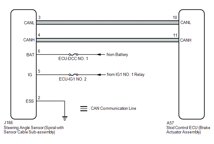
CAUTION / NOTICE / HINT

NOTICE:

Inspect the fuses for circuits related to this system before performing the following procedure.

PROCEDURE

1.

CHECK HARNESS AND CONNECTOR (POWER SOURCE TERMINAL)

(a) Remove the steering wheel and column cover.

*a

Front view of wire harness connector

(to Steering Angle Sensor (Spiral with Sensor Cable Sub-assembly))

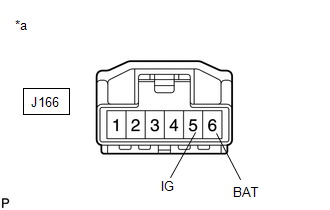
(b) Make sure that there is no looseness at the locking part and the connecting part of the connector.

OK:

The connector is securely connected.

(c) Disconnect the J166 steering angle sensor (spiral with sensor cable sub-assembly) connector.

(d) Check both the connector case and the terminals for deformation and corrosion.

OK:

No deformation or corrosion.

(e) Measure the voltage according to the value(s) in the table below.

Standard Voltage:

Tester Connection

Condition

Specified Condition

J166-6 (BAT) - Body ground

Always

11 to 14 V

J166-5 (IG) - Body ground

Ignition switch ON

11 to 14 V

NG

REPAIR OR REPLACE HARNESS OR CONNECTOR (POWER SOURCE CIRCUIT)

OK

2.

CHECK HARNESS AND CONNECTOR (GROUND TERMINAL)

(a) Turn the ignition switch off.

*a

Front view of wire harness connector

(to Steering Angle Sensor (Spiral with Sensor Cable Sub-assembly))

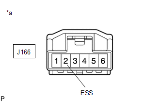
(b) Measure the resistance according to the value(s) in the table below.

NOTICE:

Before measuring the resistance of the steering angle sensor (spiral with sensor cable sub-assembly), turn the ignition switch off and leave the vehicle for 1 minute or more without operating the key or switches, or opening or closing the doors.

Standard Resistance:

Tester Connection

Condition

Specified Condition

J166-2 (ESS) - Body ground

1 minute after ignition switch off

Below 1 Ω

OK

REPLACE SPIRAL WITH SENSOR CABLE SUB-ASSEMBLY

NG

REPAIR OR REPLACE HARNESS OR CONNECTOR (GROUND CIRCUIT)

    Brake Pedal Load Sensing Switch OFF Stuck Malfunction (C1430,C1431)

    Steering Angle Sensor Internal Circuit (C1433)

    See More:

    Toyota Tundra Service Manual > Power Window Control System(w/ Jam Protection Function): Rear Power Window LH does not Operate with Rear Power Window Switch LH
    DESCRIPTION If the rear LH side manual UP/DOWN function does not operate, there may be a malfunction in the rear switch LH, the rear motor LH, the master switch, or the harness or connector. WIRING DIAGRAM CAUTION / NOTICE / HINT NOTICE: Inspect the fuses for circuits related to this system before p ...

    Toyota Tundra Owners Manual

    Toyota Tundra Service Manual

    © 2024 Copyright www.ttundra.com
    0.0369