
Toyota Tundra Service Manual: Components

COMPONENTS

ILLUSTRATION
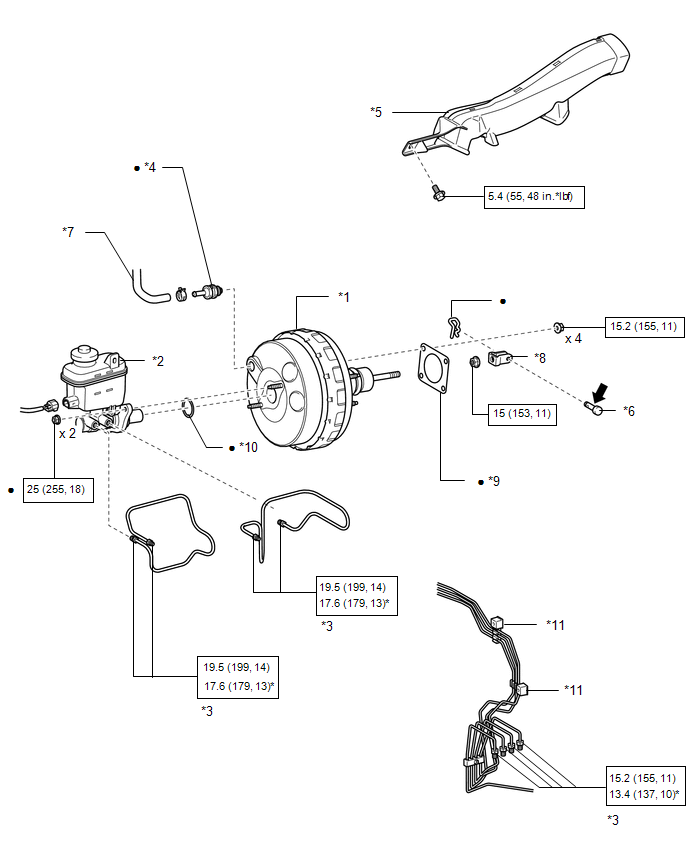
*1

BRAKE BOOSTER ASSEMBLY

*2

BRAKE MASTER CYLINDER SUB-ASSEMBLY

*3

BRAKE TUBE

*4

BRAKE VACUUM CHECK VALVE ASSEMBLY

*5

NO. 3 AIR DUCT SUB-ASSEMBLY

*6

PUSH ROD PIN

*7

VACUUM HOSE ASSEMBLY

*8

CLEVIS

*9

BRAKE BOOSTER GASKET

*10

BRAKE MASTER CYLINDER SEAL

*11

NO. 2 BRAKE TUBE CLAMP

-

-

N*m (kgf*cm, ft.*lbf): Specified torque

*

For use with a union nut wrench

Non-reusable part

Lithium soap base glycol grease

    Brake Booster

    Installation

    See More:

    Toyota Tundra Service Manual > Steering Gear: Disassembly
    DISASSEMBLY PROCEDURE 1. FIX POWER STEERING GEAR ASSEMBLY (a) Using SST, secure the power steering gear. SST: 09612-00012 HINT: Tape SST before use. NOTICE: When using a vise, do not overtighten it. 2. REMOVE TIE ROD END SUB-ASSEMBLY LH (a) Put matchmarks on the tie rod end LH and steering rack end. ...

    Toyota Tundra Owners Manual

    Toyota Tundra Service Manual

    © 2026 Copyright www.ttundra.com
    0.012