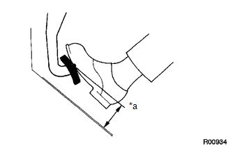
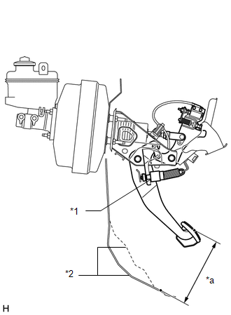
ADJUSTMENT PROCEDURE 1. CHECK BRAKE PEDAL HEIGHT (a) Check the brake pedal height. (1) Turn back the carpet. (2) Remove the tibia pad.
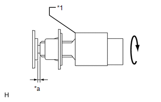
2. CHECK AND ADJUST STOP LIGHT SWITCH ASSEMBLY HINT: If the pedal height is incorrect, check and adjust the stop light switch clearance. (a) Disconnect the stop light switch connector. (b) Turn the stop light switch assembly counterclockwise and remove it.
(d) Make a quarter turn clockwise to install the stop light switch assembly. HINT: Due to the inverse screw structure, if the stop light switch assembly is turned clockwise, the stop light switch assembly moves in the direction to be pulled out. NOTICE: The turning torque for installing the stop light switch assembly should be 1.5 N*m (15 kgf*cm, 13 in.*lbf) or less. (e) Connect the stop light switch connector. (f) Check the protrusion of the rod. Standard protrusion of the rod: 1.5 to 2.5 mm (0.0591 to 0.0984 in.) 3. CHECK PEDAL FREE PLAY
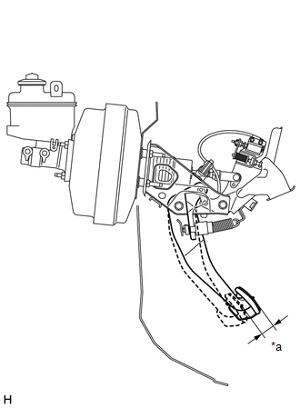
(b) Push in the brake pedal until the beginning of the resistance is felt. Measure the distance as shown in the illustration. Standard pedal free play: 1.0 to 6.0 mm (0.0394 to 0.236 in.) 4. CHECK PEDAL RESERVE DISTANCE (a) Release the parking brake pedal.
|
Toyota Tundra Service Manual > Navigation System: HD Radio Tuner Malfunction (B1551,B15A0,B15AD,B15B0,B15B3,B15B4,B15B7)
DESCRIPTION These DTCs are stored when a malfunction occurs in the navigation receiver assembly. DTC Code DTC Detection Condition Trouble Area B1551 When one of the conditions below is met: "HD Radio" tuner decoder malfunction "HD Radio" tuner audio output section malfunction "HD Radio" tuner decode ...

 ).
).