
Toyota Tundra Service Manual: Components

COMPONENTS

ILLUSTRATION
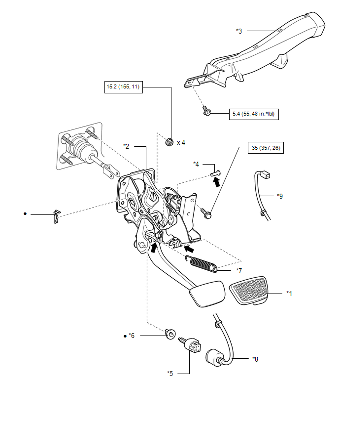
*1

BRAKE PEDAL PAD

*2

BRAKE PEDAL SUPPORT ASSEMBLY

*3

NO. 3 AIR DUCT SUB-ASSEMBLY

*4

PUSH ROD PIN

*5

STOP LIGHT SWITCH ASSEMBLY

*6

STOP LIGHT SWITCH MOUNTING ADJUSTER

*7

BRAKE PEDAL RETURN SPRING

*8

STOP LIGHT SWITCH WIRE HARNESS

*9

WIRE HARNESS

-

-

N*m (kgf*cm, ft.*lbf): Specified torque

Non-reusable part

Lithium soap base glycol grease

-

-

    Adjustment

    Installation

    See More:

    Toyota Tundra Service Manual > Air Conditioning System(for Manual Air Conditioning System): IG Power Source Circuit
    DESCRIPTION When the ignition switch is turned ON, positive (+) battery voltage is applied to the air conditioning amplifier. WIRING DIAGRAM PROCEDURE 1. INSPECT FUSE (ECU-IG1 NO.3) (a) Remove the ECU-IG1 NO.3 fuse from the driver side junction block. (b) Measure the resistance according to the valu ...

    Toyota Tundra Owners Manual

    Toyota Tundra Service Manual

    © 2026 Copyright www.ttundra.com
    0.0105