INSTALLATION PROCEDURE 1. INSTALL NO. 2 CABLE SUPPORT BRACKET
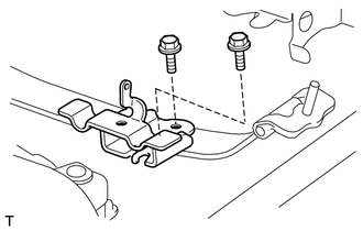
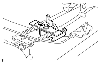
2. INSTALL PARKING BRAKE INTERMEDIATE LEVER SUB-ASSEMBLY (a) Apply MP grease to the moving parts of the parking brake intermediate lever sub-assembly. 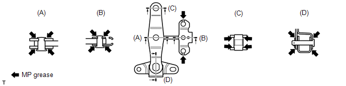 (b) Apply MP grease to the areas where the cables contact the parking brake intermediate lever sub-assembly.
(d) Install the parking brake intermediate lever sub-assembly with parking brake intermediate lever bracket with the 2 bolts. Torque: 19 N·m {194 kgf·cm, 14 ft·lbf} 3. INSTALL NO. 3 PARKING BRAKE CABLE ASSEMBLY
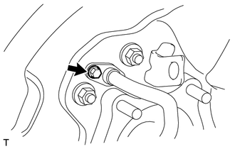
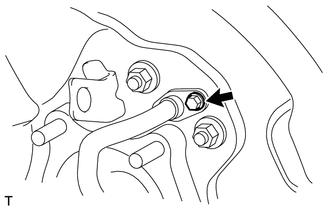
(b) Connect the No. 3 parking brake cable assembly to the parking brake intermediate lever sub-assembly (labeled C) and install the 6 bolts (labeled A and B). 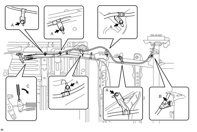 Torque: for bolt A : 19 N·m {194 kgf·cm, 14 ft·lbf} for bolt B : 14 N·m {138 kgf·cm, 10 ft·lbf} NOTICE: Do not bend and twist the parking brake cable. 4. INSTALL PARKING BRAKE SHOE LEVER LH
5. INSTALL NO. 2 PARKING BRAKE SHOE ASSEMBLY LH 6. INSTALL NO. 1 PARKING BRAKE SHOE ASSEMBLY LH 7. INSTALL PARKING BRAKE SHOE RETURN SPRING LH 8. CHECK PARKING BRAKE INSTALLATION 9. INSTALL REAR DISC LH
10. ADJUST PARKING BRAKE SHOE CLEARANCE 11. CONNECT REAR DISC BRAKE CYLINDER ASSEMBLY LH 12. INSTALL REAR WHEEL LH
13. INSTALL NO. 2 PARKING BRAKE CABLE ASSEMBLY
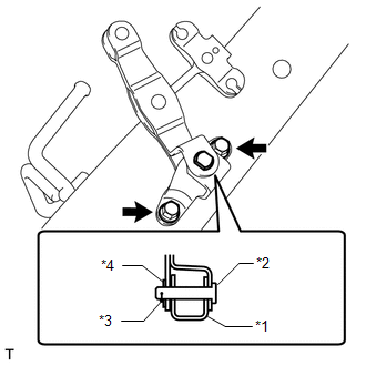
(b) Install the No. 2 parking brake cable clamp with the bolt (labeled A). 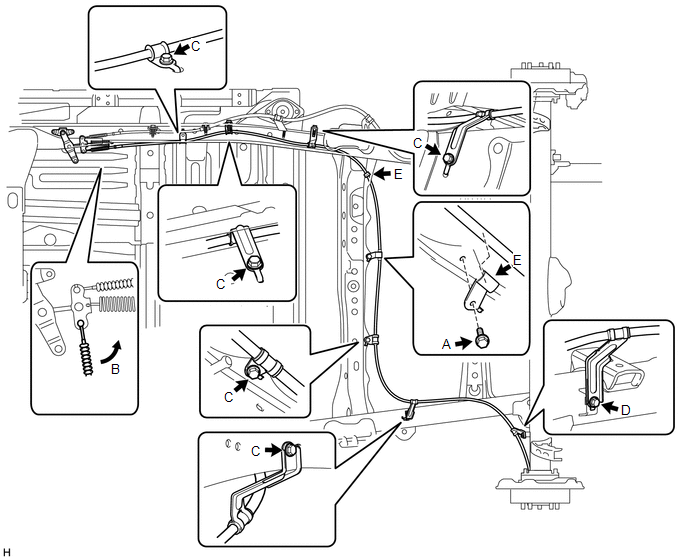 Torque: 19 N·m {194 kgf·cm, 14 ft·lbf} (c) Connect the No. 2 parking brake cable assembly to the parking brake intermediate lever sub-assembly (labeled B) and install the 6 bolts (labeled C and D). NOTICE: Do not bend and twist the parking brake cable. Torque: for bolt C : 19 N·m {194 kgf·cm, 14 ft·lbf} for bolt D : 14 N·m {138 kgf·cm, 10 ft·lbf} (d) Connect the No. 2 parking brake cable assembly to the 2 No. 2 parking brake clamps (labeled E). 14. INSTALL NO. 2 CABLE RETAINER
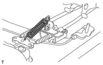
15. INSTALL INTERMEDIATE LEVER TENSION SPRING
16. INSTALL PARKING BRAKE SHOE LEVER RH HINT: Use the same procedures described for the LH side. 17. INSTALL NO. 2 PARKING BRAKE SHOE ASSEMBLY RH HINT: Use the same procedures described for the LH side. 18. INSTALL NO. 1 PARKING BRAKE SHOE ASSEMBLY RH HINT: Use the same procedures described for the LH side. 19. INSTALL PARKING BRAKE SHOE RETURN SPRING RH HINT: Use the same procedures described for the LH side. 20. CHECK PARKING BRAKE INSTALLATION 21. INSTALL REAR DISC RH HINT: Use the same procedures described for the LH side. 22. ADJUST PARKING BRAKE SHOE CLEARANCE
23. CONNECT REAR DISC BRAKE CYLINDER ASSEMBLY RH HINT: Use the same procedures described for the LH side. 24. INSTALL REAR WHEEL RH 25. INSTALL NO. 1 PARKING BRAKE CABLE ASSEMBLY (for 3700 mm [12 ft. 1.7 in.] Wheelbase Type) (a) Install the No. 1 cable support bracket with the 3 bolts (labeled A). 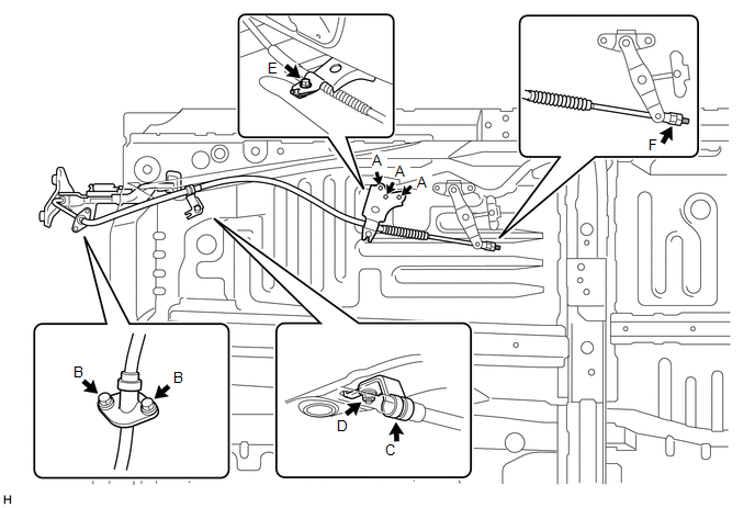 Torque: 19 N·m {194 kgf·cm, 14 ft·lbf} (b) Install the No. 1 parking brake cable assembly to the inside of the vehicle with the 2 bolts (labeled B). Torque: 5.4 N·m {55 kgf·cm, 48 in·lbf} (c) Connect the No. 1 parking brake cable clamp (labeled C) to the No. 1 parking brake cable assembly. (d) Install the No. 1 parking brake cable clamp with the nut (labeled D). Torque: 5.4 N·m {55 kgf·cm, 48 in·lbf} (e) Install the No. 1 parking brake cable assembly and cable retainer with the bolt (labeled E). Torque: 13 N·m {127 kgf·cm, 9 ft·lbf} (f) Temporarily install the adjustment nut and lock nut (labeled F). NOTICE: Do not bend and twist the parking brake cable. HINT: The nuts will be tightened to a torque specification in the "ADJUST PARKING BRAKE PEDAL TRAVEL" procedure. 26. INSTALL NO. 1 PARKING BRAKE CABLE ASSEMBLY (for 4180 mm [13 ft. 8.6 in.] Wheelbase Type) (a) Install the No. 1 cable support bracket with the 3 bolts (labeled A). 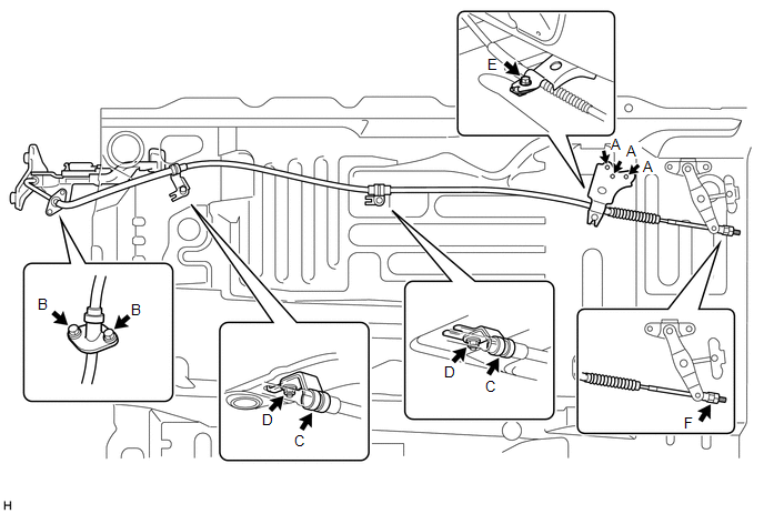 Torque: 19 N·m {194 kgf·cm, 14 ft·lbf} (b) Install the No. 1 parking brake cable assembly to the inside of the vehicle with the 2 bolts (labeled B). Torque: 5.4 N·m {55 kgf·cm, 48 in·lbf} (c) Connect the 2 No. 1 parking brake cable clamps (labeled C) to the No. 1 parking brake cable assembly. (d) Install the 2 No. 1 parking brake cable clamps with the 2 nuts (labeled D). Torque: 5.4 N·m {55 kgf·cm, 48 in·lbf} (e) Install the No. 1 parking brake cable assembly and cable retainer with the bolt (labeled E). Torque: 13 N·m {127 kgf·cm, 9 ft·lbf} (f) Temporarily install the adjustment nut and lock nut (labeled F). NOTICE: Do not bend and twist the parking brake cable. HINT: The nuts will be tightened to a torque specification in the "ADJUST PARKING BRAKE PEDAL TRAVEL" procedure. 27. INSTALL FRONT NO. 2 EXHAUST PIPE ASSEMBLY (a) for 1UR-FE: Install the front No. 2 exhaust pipe (See page
(b) for 3UR-FE: Install the front No. 2 exhaust pipe (See page
(c) for 3UR-FBE: Install the front No. 2 exhaust pipe (See page
28. CONNECT NO. 1 PARKING BRAKE CABLE ASSEMBLY 29. SETTLE PARKING BRAKE SHOE AND DISC 30. CHECK PARKING BRAKE PEDAL TRAVEL 31. ADJUST PARKING BRAKE PEDAL TRAVEL 32. INSTALL LOWER NO. 1 INSTRUMENT PANEL AIRBAG ASSEMBLY 33. INSTALL LOWER INSTRUMENT PANEL FINISH PANEL SUB-ASSEMBLY LH 34. INSTALL INSTRUMENT SIDE PANEL LH 35. CONNECT CABLE TO NEGATIVE BATTERY TERMINAL 36. CHECK SRS WARNING LIGHT (a) Check the SRS warning light (See page
37. INSPECT FOR EXHAUST GAS LEAK (a) If gas is leaking, tighten the areas necessary to stop the leak. Replace damaged parts as necessary. |
Toyota Tundra Service Manual > Can Communication System: Check Bus 3 Lines for Short Circuit
DESCRIPTION There may be a short circuit between the bus 3 CAN main wires and/or CAN branch wires when the resistance between terminals 6 (CA3H) and 21 (CA3L) or 19 (CAYH) and 20 (CAYL) of the central gateway ECU (network gateway ECU) is below 54 Ω. Symptom Trouble Area *1: w/ Audio and Visual Syst ...