REMOVAL PROCEDURE 1. PRECAUTION NOTICE: After
turning the ignition switch off, waiting time may be required before
disconnecting the cable from the battery terminal. Therefore, make sure
to read the disconnecting the cable from the battery terminal notice
before proceeding with work (See page 2. DISCONNECT CABLE FROM NEGATIVE BATTERY TERMINAL CAUTION: Wait at least 90 seconds after disconnecting the cable from the negative (-) battery terminal to disable the SRS system. 3. REMOVE INSTRUMENT SIDE PANEL LH 4. REMOVE LOWER INSTRUMENT PANEL FINISH PANEL SUB-ASSEMBLY LH 5. REMOVE LOWER NO. 1 INSTRUMENT PANEL AIRBAG ASSEMBLY 6. RELEASE PARKING BRAKE PEDAL 7. DISCONNECT NO. 1 PARKING BRAKE CABLE ASSEMBLY
8. REMOVE FRONT NO. 2 EXHAUST PIPE ASSEMBLY (a) for 1UR-FE: Remove the front No. 2 exhaust pipe (See page
(b) for 3UR-FE: Remove the front No. 2 exhaust pipe (See page
(c) for 3UR-FBE: Remove the front No. 2 exhaust pipe (See page
9. REMOVE NO. 1 PARKING BRAKE CABLE ASSEMBLY (for 3700 mm [12 ft. 1.7 in.] Wheelbase Type) (a) Remove the adjustment nut and lock nut (labeled A). 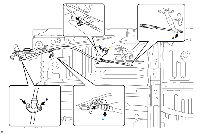 (b) Remove the bolt (labeled B) and cable retainer. (c) Remove the nut (labeled C) and No. 1 parking brake cable clamp from the body. (d) Disconnect the No. 1 parking brake cable clamp (labeled D) from the No. 1 parking brake cable assembly. (e) Remove the 2 bolts (labeled E) and No. 1 parking brake cable assembly from the inside of the vehicle. NOTICE: Do not bend and twist the parking brake cable. (f) Remove the 3 bolts (labeled F) and No. 1 cable support bracket. 10. REMOVE NO. 1 PARKING BRAKE CABLE ASSEMBLY (for 4180 mm [13 ft. 8.6 in.] Wheelbase Type) (a) Remove the adjustment nut and lock nut (labeled A). 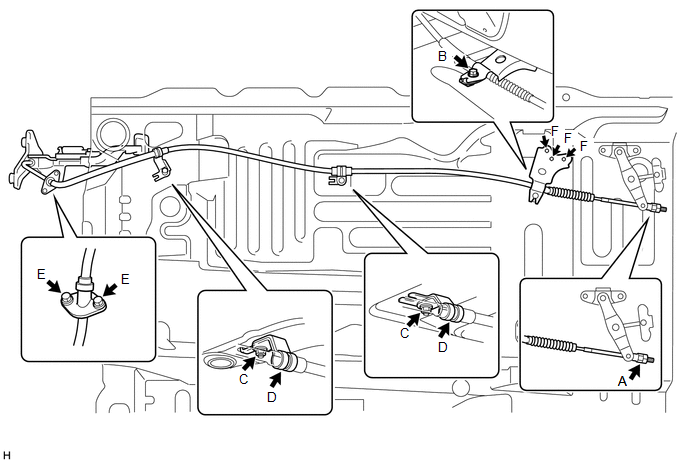 (b) Remove the bolt (labeled B) and cable retainer. (c) Remove the 2 nuts (labeled C) and 2 No. 1 parking brake cable clamps from the body. (d) Disconnect the 2 No. 1 parking brake cable clamps (labeled D) from the No. 1 parking brake cable assembly. (e) Remove the 2 bolts (labeled E) and No. 1 parking brake cable assembly from the inside of the vehicle. NOTICE: Do not bend and twist the parking brake cable. (f) Remove the 3 bolts (labeled F) and No. 1 cable support bracket. 11. REMOVE REAR WHEEL LH 12. DISCONNECT REAR DISC BRAKE CYLINDER ASSEMBLY LH 13. REMOVE REAR DISC LH
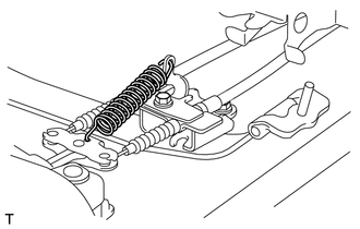
14. REMOVE PARKING BRAKE SHOE RETURN SPRING LH 15. REMOVE NO. 1 PARKING BRAKE SHOE ASSEMBLY LH 16. REMOVE NO. 2 PARKING BRAKE SHOE ASSEMBLY LH 17. REMOVE PARKING BRAKE SHOE LEVER LH 18. REMOVE INTERMEDIATE LEVER TENSION SPRING
19. REMOVE NO. 2 CABLE RETAINER
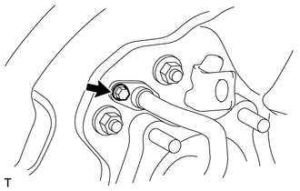
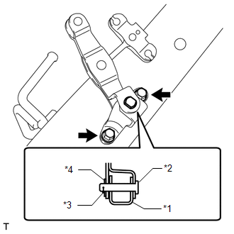
20. REMOVE NO. 3 PARKING BRAKE CABLE ASSEMBLY (a) Remove the 6 bolts (labeled A and B) and disconnect the No. 3 parking brake cable assembly from the parking brake intermediate lever sub-assembly (labeled C). NOTICE: Do not bend and twist the parking brake cable. 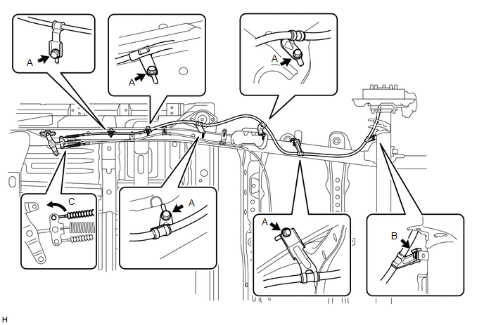
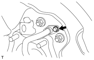
21. REMOVE REAR WHEEL RH 22. DISCONNECT REAR DISC BRAKE CYLINDER ASSEMBLY RH HINT: Use the same procedures described for the LH side. 23. REMOVE REAR DISC RH HINT: Use the same procedures described for the LH side. 24. REMOVE PARKING BRAKE SHOE RETURN SPRING RH HINT: Use the same procedures described for the LH side. 25. REMOVE NO. 1 PARKING BRAKE SHOE ASSEMBLY RH HINT: Use the same procedures described for the LH side. 26. REMOVE NO. 2 PARKING BRAKE SHOE ASSEMBLY RH HINT: Use the same procedures described for the LH side. 27. REMOVE PARKING BRAKE SHOE LEVER RH HINT: Use the same procedures described for the LH side. 28. REMOVE NO. 2 PARKING BRAKE CABLE ASSEMBLY (a) Disconnect the No. 2 parking brake cable assembly from the 2 clamps (labeled A). 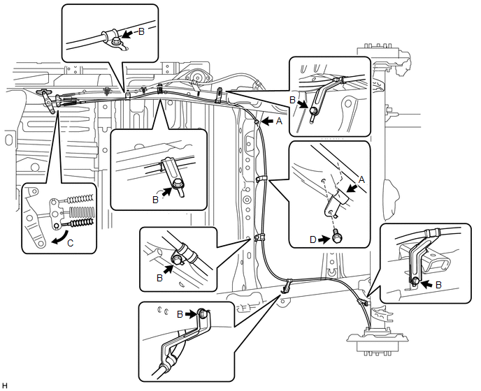 (b) Remove the 6 bolts (labeled B) and disconnect the No. 2 parking brake cable assembly from the parking brake intermediate lever sub-assembly (labeled C). NOTICE: Do not bend and twist the parking brake cable. (c) Remove the bolt (labeled D) and clamp.
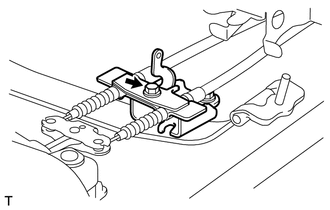
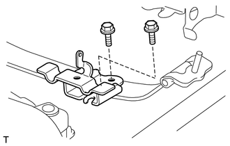
29. REMOVE PARKING BRAKE INTERMEDIATE LEVER SUB-ASSEMBLY
(b) Remove the clip, washer, pin and parking brake intermediate lever sub-assembly from the parking brake intermediate lever bracket. 30. REMOVE NO. 2 CABLE SUPPORT BRACKET
|
Toyota Tundra Service Manual > Audio And Visual System: Illumination Circuit
DESCRIPTION Power is supplied to the radio and display receiver assembly and steering pad switch assembly illumination when the light control switch is in the tail or head position. WIRING DIAGRAM CAUTION / NOTICE / HINT NOTICE: The vehicle is equipped with a Supplemental Restraint System (SRS) whic ...