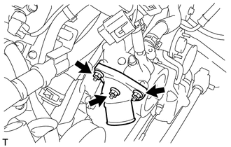
INSTALLATION PROCEDURE 1. INSTALL WATER INLET SUB-ASSEMBLY WITH THERMOSTAT
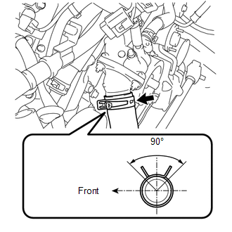
2. CONNECT OUTLET RADIATOR HOSE
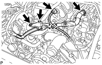
3. INSTALL AIR TUBE SUB-ASSEMBLY LH
(b) Connect the vacuum sensor connector and clamp.
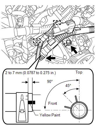
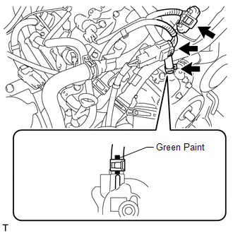
(d) Connect the air hose. (e) Connect the 2 wire harness clamps. HINT: When installing the hose, make sure the paint mark and clip are as shown in the illustration.
4. ADD ENGINE COOLANT 5. INSPECT FOR COOLANT LEAK 6. INSTALL AIR CLEANER ASSEMBLY 7. INSTALL V-BANK COVER SUB-ASSEMBLY 8. INSTALL NO. 1 ENGINE UNDER COVER |
Toyota Tundra Owners Manual > Steps to take in an
emergency: If your vehicle overheats
The following may indicate that your vehicle is overheating: The needle of the engine coolant temperature gauge enters the red zone or a loss of engine power is experienced. (For example, the vehicle speed does not increase.) "ENGINE COOLANT OVERTEMP" is shown on the multi-information display. Stea ...