Toyota Tundra Service Manual: Inspection

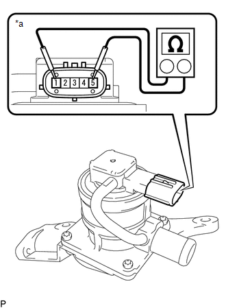
INSPECTION

PROCEDURE

1. INSPECT AIR SWITCHING VALVE ASSEMBLY

(a) Measure the resistance according to the value(s) in the table below.

Standard Resistance:

Tester Connection

Condition

Specified Condition

1 - 5

20°C (68°F)

4.5 to 5.5 Ω

1 - Body ground

Always

1 MΩ or higher

5 - Body ground

Text in Illustration

*a

Component without harness connected

(Air Switching Valve Assembly)

NOTICE:

When measuring the resistance, do not touch terminals 2, 3 or 4.

HINT:

When measuring the resistance, make sure that the surface temperature of the air switching valve assembly is 20°C (68°F).

If the result is not as specified, replace the air switching valve assembly.

(b) Check the operation of the air switching valve assembly.

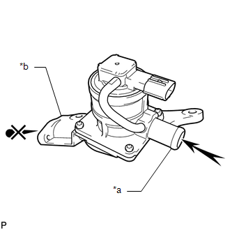
(1) Check that air does not flow from port A to port B.

Text in Illustration

*a

Port A

*b

Port B

Air

NOTICE:

Make sure the applied pressure is 30 kPa (0.3 kgf/cm2, 4.4 psi) or less.

If the result is not as specified, replace the air switching valve assembly.

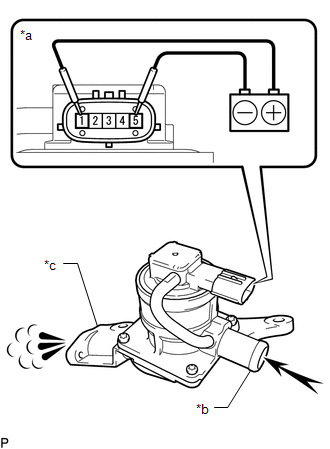
(2) Apply battery voltage across terminals 1 and 5.

Text in Illustration

*a

Component without harness connected

(Air Switching Valve Assembly)

*b

Port A

*c

Port B

Air

NOTICE:

When applying voltage, do not touch terminals 2, 3 or 4.

(3) Check that air flows from port A to port B.

If the result is not as specified, replace the air switching valve assembly.

    Components

    Installation

    See More:

    Toyota Tundra Service Manual > Air Conditioning System(for Manual Air Conditioning System): Evaporator Temperature Sensor Circuit (B1413/13)
    DESCRIPTION The No. 1 cooler thermistor is installed on the evaporator in the air conditioner unit to detect the cooled air temperature that has passed through the evaporator and control the air conditioning. It sends appropriate signals to the air conditioning amplifier. The resistance of the No. 1 ...

    Toyota Tundra Owners Manual

    Toyota Tundra Service Manual

    © 2025 Copyright www.ttundra.com
    0.0093