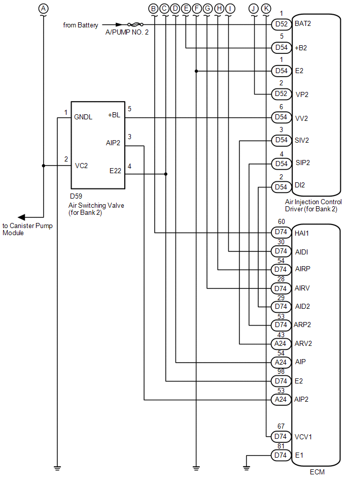
SYSTEM DIAGRAM 1. SECONDARY AIR INJECTION CONTROL SYSTEM DIAGRAM 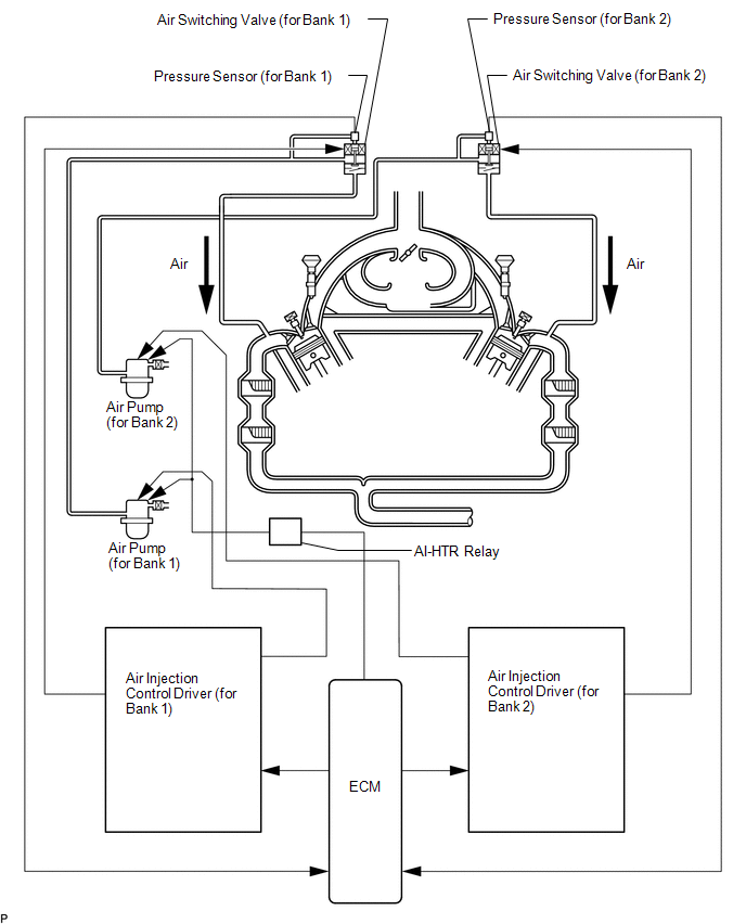 2. SECONDARY AIR INJECTION SYSTEM WIRING DIAGRAM 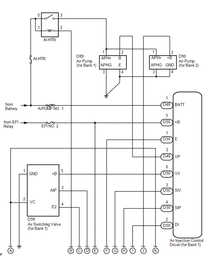
 3. EGR CONTROL SYSTEM DIAGRAM  4. EGR CONTROL SYSTEM WIRING DIAGRAM 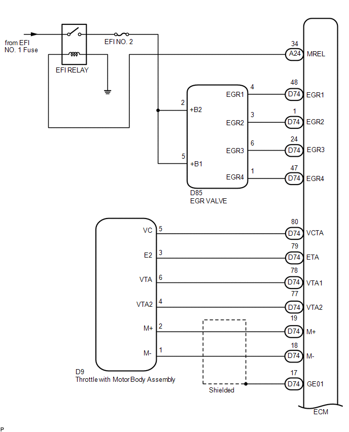
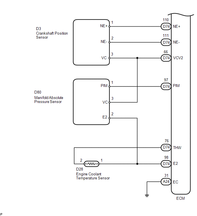 5. EVAP CONTROL SYSTEM DIAGRAM 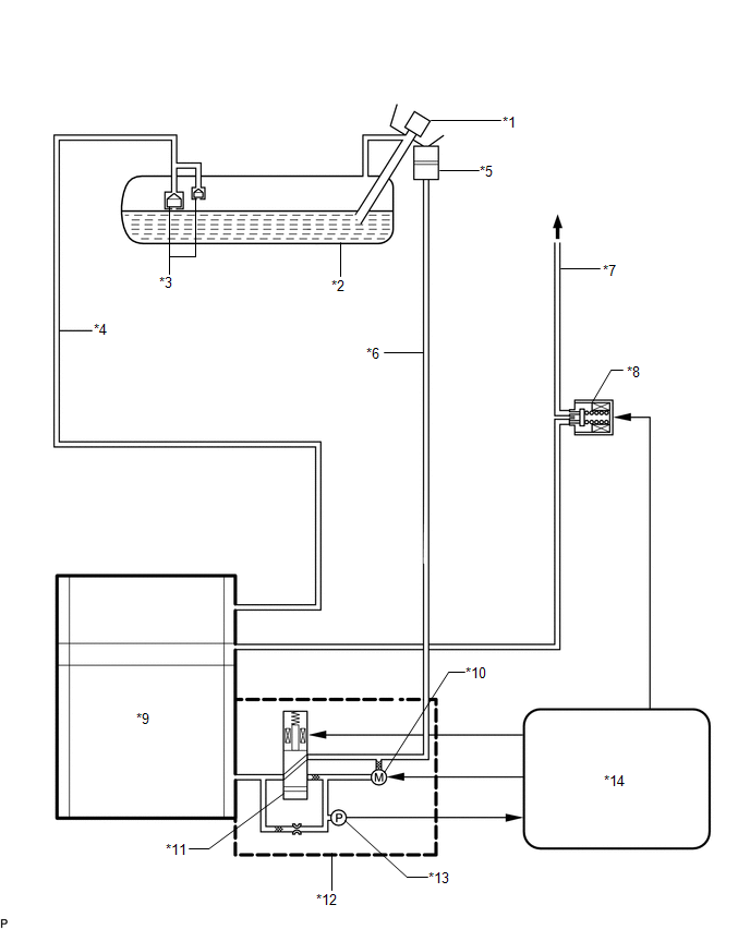 Text in Illustration Text in Illustration
6. EVAP CONTROL SYSTEM WIRING DIAGRAM 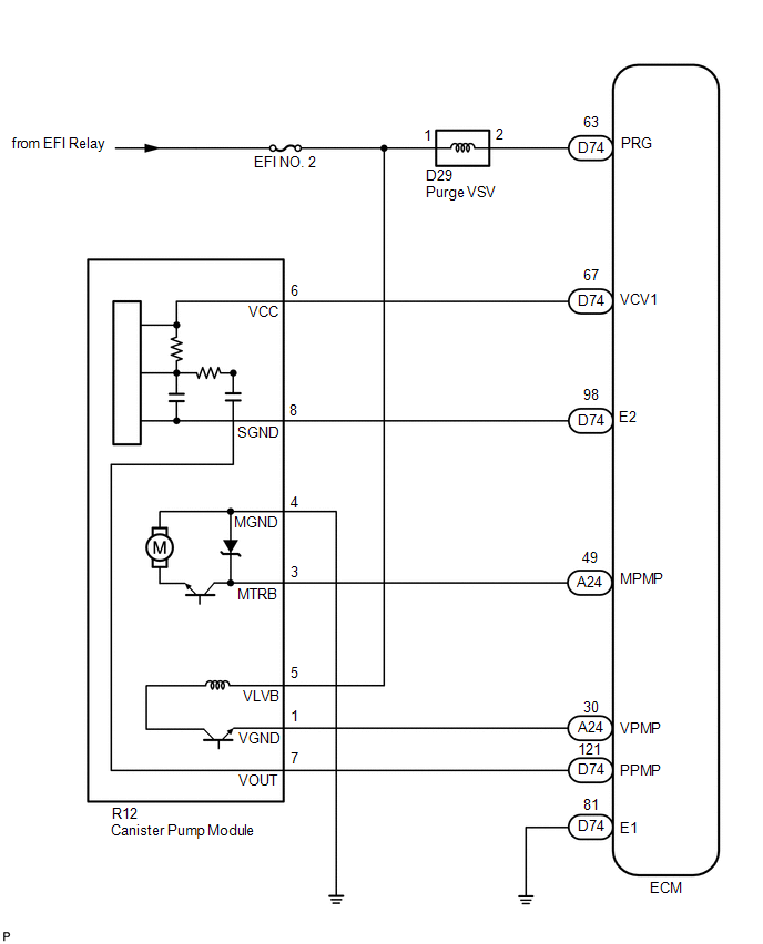 |
Toyota Tundra Service Manual > Generator: Installation
INSTALLATION PROCEDURE 1. INSTALL GENERATOR ASSEMBLY (a) Install the generator with the 3 bolts and nut. Torque: 43 N·m {438 kgf·cm, 32 ft·lbf} (b) Install the harness bracket to the generator with the bolt. Torque: 31 N·m {316 kgf·cm, 23 ft·lbf} (c) Connect the generator connector. (d) Connec ...


