INSTALLATION PROCEDURE 1. INSTALL CAMSHAFT TIMING OIL CONTROL VALVE ASSEMBLY (for Exhaust Side of Bank 1) 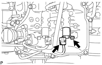 (a) Apply a light coat of engine oil to the O-ring. (b) Install a new O-ring to the oil control valve. (c) Install the oil control valve with the bolt. Torque: 10 N·m {102 kgf·cm, 7 ft·lbf} (d) Connect the oil control valve connector. 2. INSTALL CAMSHAFT TIMING OIL CONTROL VALVE ASSEMBLY (for Intake Side of Bank 1) 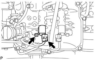 (a) Apply a light coat of engine oil to the O-ring. (b) Install a new O-ring to the oil control valve. (c) Install the oil control valve with the bolt. Torque: 10 N·m {102 kgf·cm, 7 ft·lbf} (d) Connect the oil control valve connector. 3. INSTALL CAMSHAFT TIMING OIL CONTROL VALVE ASSEMBLY (for Intake Side of Bank 2) 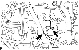 (a) Apply a light coat of engine oil to the O-ring. (b) Install a new O-ring to the oil control valve. (c) Install the oil control valve with the bolt. Torque: 10 N·m {102 kgf·cm, 7 ft·lbf} (d) Connect the oil control valve connector. 4. INSTALL CAMSHAFT TIMING OIL CONTROL VALVE ASSEMBLY (for Exhaust Side of Bank 2) 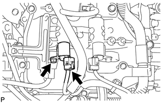 (a) Apply a light coat of engine oil to the O-ring. (b) Install a new O-ring to the oil control valve. (c) Install the oil control valve with the bolt. Torque: 10 N·m {102 kgf·cm, 7 ft·lbf} (d) Connect the oil control valve connector. 5. INSTALL AIR CLEANER HOSE ASSEMBLY 6. INSTALL V-BANK COVER SUB-ASSEMBLY |
Toyota Tundra Service Manual > Can Communication System: Dtc Combination Table
DTC COMBINATION TABLE HOW TO INTERPRET COMMUNICATION DTCS (DTCS THAT START WITH U) (a) If a CAN communication error cannot be reproduced, determine the suspected malfunctioning part using the DTCs stored in ECUs that are connected to the CAN buses by following the procedure below. HINT: Communicatio ...


