REMOVAL PROCEDURE 1. REMOVE V-BANK COVER SUB-ASSEMBLY 2. REMOVE AIR CLEANER HOSE ASSEMBLY 3. REMOVE CAMSHAFT TIMING OIL CONTROL VALVE ASSEMBLY (for Exhaust Side of Bank 1) 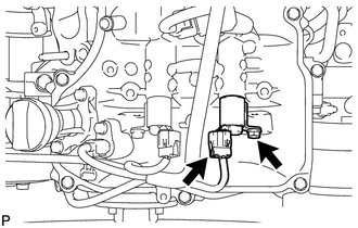 (a) Disconnect the oil control valve connector. (b) Remove the bolt and oil control valve. (c) Remove the O-ring from the oil control valve. 4. REMOVE CAMSHAFT TIMING OIL CONTROL VALVE ASSEMBLY (for Intake Side of Bank 1) 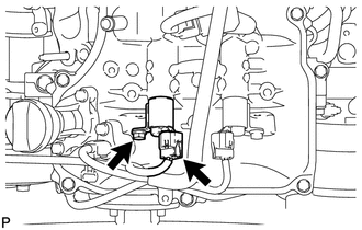 (a) Disconnect the oil control valve connector. (b) Remove the bolt and oil control valve. (c) Remove the O-ring from the oil control valve. 5. REMOVE CAMSHAFT TIMING OIL CONTROL VALVE ASSEMBLY (for Intake Side of Bank 2)  (a) Disconnect the oil control valve connector. (b) Remove the bolt and oil control valve. (c) Remove the O-ring from the oil control valve. 6. REMOVE CAMSHAFT TIMING OIL CONTROL VALVE ASSEMBLY (for Exhaust Side of Bank 2) 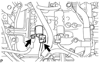 (a) Disconnect the oil control valve connector. (b) Remove the bolt and oil control valve. (c) Remove the O-ring from the oil control valve. |
Toyota Tundra Service Manual > Navigation System: Speaker Circuit
DESCRIPTION The navigation receiver assembly sends sound signals to the speakers. WIRING DIAGRAM PROCEDURE 1. CHECK VEHICLE CONDITION (a) Check the vehicle condition. Result Result Proceed to for 7 or 9 Speakers A for 12 Speakers B B GO TO STEP 9 A 2. CHECK HARNESS AND CONNECTOR (SPEAKER CIRCUIT) *1 ...


