Components COMPONENTS ILLUSTRATION 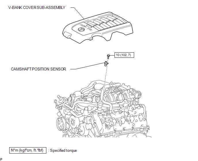 Installation INSTALLATION PROCEDURE 1. INSTALL CAMSHAFT POSITION SENSOR  (a) Install the sensor with the bolt. Torque: 10 N·m {102 kgf·cm, 7 ft·lbf} (b) Connect the sensor connector. 2. INSTALL V-BANK COVER SUB-ASSEMBLY Removal REMOVAL PROCEDURE 1. REMOVE V-BANK COVER SUB-ASSEMBLY 2. REMOVE CAMSHAFT POSITION SENSOR 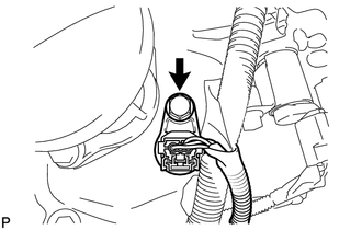 (a) Disconnect the sensor connector. (b) Remove the bolt and sensor. |
Toyota Tundra Service Manual > Power Window Control System(w/o Jam Protection Function): Rear Power Window LH does not Operate with Rear Power Window Switch LH
DESCRIPTION HINT: for Double Cab, CrewMax If the rear LH side manual UP/DOWN function does not operate, there may be a malfunction in the rear switch LH, rear motor LH, master switch or harness and connector. WIRING DIAGRAM PROCEDURE 1. CHECK HARNESS AND CONNECTOR (REAR SWITCH LH - BATTERY) (a) Disc ...


