DESCRIPTION The cranking holding control system keeps energizing the starter relay from when the ECM detects the starter signal (STSW signal) from the ignition switch until the ECM performs a judgment of "Engine started". Furthermore, the ECM outputs an accessory cut signal (ACCR signal) to the ACC cut relay during cranking to prevent flickering of the combination meter, clock, audio system, and so on. When the ECM detects the STSW signal, the ECM outputs the starter relay drive signal (STAR signal) to the starter relay through the park/neutral position switch, and then, the engine is cranked. When the ECM receives a stable engine speed signal (NE signal), more specifically, when the NE signal reaches a predetermined value, the ECM stops outputting the STAR signal. Also, the ECM monitors the starter relay operating conditions based on the STA terminal voltage status. 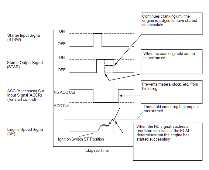 WIRING DIAGRAM 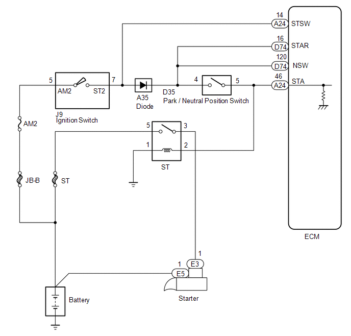 PROCEDURE
(a) Connect the Techstream to the DLC3. (b) Turn the ignition switch to ON. (c) Turn the Techstream on. (d) Enter the following menus: Powertrain / Engine and ECT / Data List / Starter Signal. (e) Check the result when the ignition switch is turned to the ON and START positions. OK:
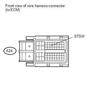 (a) Disconnect the ECM connector. (b) Perform the cranking operation. (c) Measure the voltage according to the value(s) in the table below. Standard Voltage:
HINT: DTCs related to the communication with other computers may be set due to this inspection. Clear those DTCs after the inspection.
 (a) Connect the Techstream to the DLC3. (b) Turn the ignition switch to ON. (c) Turn the Techstream on. (d) Enter the following menus: Powertrain / Engine and ECT / Active Test / Control the All Cylinders Fuel Cut. (e) Measure the voltage according to the value(s) in the table below. Standard Voltage:
HINT:
(a) Inspect Park/Neutral Position (PNP) switch assembly.
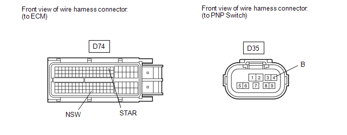 (a) Disconnect the park/neutral position (PNP) switch assembly connector. (b) Disconnect the ECM connector. (c) Measure the resistance according to the value(s) in the table below. Standard Resistance:
(a) Remove the ST relay from the engine room relay block. (b) Disconnect the park/neutral position (PNP) switch assembly switch connector. (c) Disconnect the ECM connector. (d) Measure the resistance according to the value(s) in the table below. Standard Resistance:
(a) Inspect the ignition switch assembly (See page
(a) Inspect Park/Neutral Position (PNP) switch assembly.
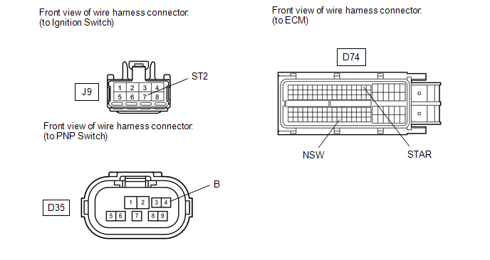 (a) Disconnect the ignition switch assembly connector. (b) Disconnect the Park/Neutral Position (PNP) switch assembly connector. (c) Disconnect the ECM connector. (d) Measure the resistance according to the value(s) in the table below. Standard Resistance :
HINT: The wire between the PNP switch and ignition switch has a diode (refer to the wiring diagram). The current flowing to the PNP switch is rectified by the diode.
(a) Remove the ST relay from the engine room relay block. (b) Disconnect the Park/Neutral Position (PNP) switch assembly connector. (c) Disconnect the ECM connector. (d) Measure the resistance according to the value(s) in the table below. Standard Resistance:
|
Toyota Tundra Service Manual > Rear Axle Shaft: Disassembly
DISASSEMBLY PROCEDURE 1. REMOVE REAR AXLE SHAFT SNAP RING (a) Using a snap ring expander, remove the snap ring. 2. REMOVE REAR AXLE SHAFT (a) Using SST and a press, press out the rear axle shaft. SST: 09521-25011 SST: 09521-60010 (b) Remove the rear axle bearing inner retainer from the axle hub. (c) ...


 )
)

