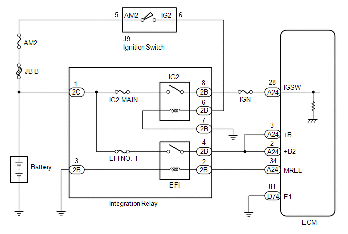
DESCRIPTION When the
ignition switch is turned to ON, the battery voltage is applied to the
IGSW terminal of the ECM. The output signal from the MREL terminal of
the ECM causes a current to flow to the coil, closing the contacts of
the integration relay (EFI relay) and supplying power to terminals +B
and +B2 of the ECM. WIRING DIAGRAM
 PROCEDURE
| 1. |
INSPECT FUSES (AM2, IG2 MAIN, EFI NO. 1, IGN) |
(a) Remove the IG2 MAIN fuse, EFI NO. 1 fuse and IGN fuse from the engine room relay block.
(b) Remove the AM2 fuse from the driver side junction block. (c) Measure the resistance according to the value(s) in the table below.
Standard Resistance: |
Tester Connection | Condition |
Specified Condition | |
AM2 fuse | Always |
Below 1 Ω | |
IG2 MAIN fuse | Always |
Below 1 Ω | |
EFI NO. 1 fuse | Always |
Below 1 Ω | |
IGN fuse | Always |
Below 1 Ω |
| NG |
 | CHECK FOR SHORT IN ALL HARNESSES AND CONNECTORS CONNECTED TO FUSE AND REPLACE FUSE |
|
OK |
 | |
| 2. |
INSPECT INTEGRATION RELAY (IG2, EFI) |
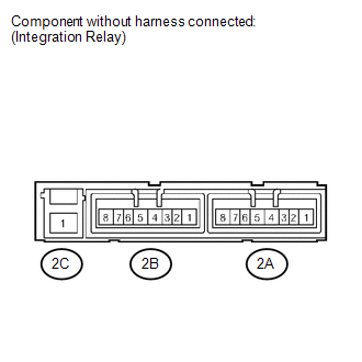 (a) Remove the integration relay from the engine room relay block.
(b) Measure the resistance according to the value(s) in the table below.
Standard Resistance: |
Tester Connection | Condition |
Specified Condition | |
2C-1 - 2B-8 | No battery voltage is applied to terminals 2B-6 and 2B-7 |
10 kΩ or higher | |
2C-1 - 2B-8 | Battery voltage is applied to terminals 2B-6 and 2B-7 |
Below 1 Ω | |
2C-1 - 2B-4 | No battery voltage is applied to terminals 2B-2 and 2B-3 |
10 kΩ or higher | |
2C-1 - 2B-4 | Battery voltage is applied to terminals 2B-2 and 2B-3 |
Below 1 Ω |
| NG |
| REPLACE INTEGRATION RELAY |
|
OK | |
| |
| 3. |
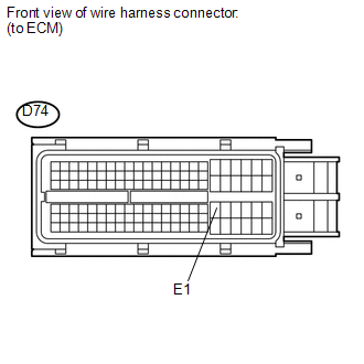
CHECK HARNESS AND CONNECTOR (ECM - BODY GROUND) |
 (a) Disconnect the ECM connector.
(b) Measure the resistance according to the value(s) in the table below.
Standard Resistance: |
Tester Connection | Condition |
Specified Condition | |
D74-81 (E1) - Body ground |
Always | Below 1 Ω |
| NG |
| REPAIR OR REPLACE HARNESS OR CONNECTOR |
|
OK | |
| |
| 4. |
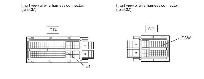
INSPECT ECM (IGSW VOLTAGE) |
 (a) Disconnect the ECM connectors.
(b) Turn the ignition switch to ON. (c) Measure the voltage according to the value(s) in the table below.
Standard Voltage: |
Tester Connection | Switch Condition |
Specified Condition | |
A24-28 (IGSW) - D74-81 (E1) |
Ignition switch ON | 11 to 14 V |
| OK |
| REPLACE ECM |
|
NG | |
| |
| 5. |
CHECK HARNESS AND CONNECTOR (RELAY BLOCK - ECM, IGNITION SWITCH, BATTERY AND BODY GROUND) |
(a) Disconnect the ECM connector. (b) Disconnect the ignition switch connector.
(c) Disconnect the cable from the battery negative (-) terminal. (d) Disconnect the cable from the battery positive (+) terminal.
(e) Remove the AM2 fuse and integration relay. (f) Measure the resistance according to the value(s) in the table below.
Standard Resistance: |
Tester Connection | Condition |
Specified Condition | |
A24-28 (IGSW) - 2B-8 |
Always | Below 1 Ω | |
2B-7 - Body ground | Always |
Below 1 Ω | |
Positive (+) battery cable - 2C-1 |
Always | Below 1 Ω | |
Positive (+) battery cable - AM2 fuse terminal 1 |
Always | Below 1 Ω | |
J9-5 (AM2) - AM2 fuse terminal 2 |
Always | Below 1 Ω | |
J9-6 (IG2) - 2B-6 | Always |
Below 1 Ω | |
A24-28 (IGSW) or 2B-8 - Body ground |
Always | 10 kΩ or higher | |
Positive (+) battery cable or 2C-1 - Body ground |
Always | 10 kΩ or higher | |
Positive (+) battery cable or AM2 fuse terminal 1 - Body ground |
Always | 10 kΩ or higher | |
J9-5 (AM2) or AM2 fuse terminal 2 - Body ground |
Always | 10 kΩ or higher | |
J9-6 (IG2) or 2B-6 - Body ground |
Always | 10 kΩ or higher |
| NG |
| REPAIR OR REPLACE HARNESS OR CONNECTOR |
|
OK | |
| |
| 6. |
INSPECT IGNITION SWITCH | (a) Inspect the ignition switch (See page
 ). ).
| NG | |
REPLACE IGNITION SWITCH |
|
OK | |
| |
| 7. |
CHECK HARNESS AND CONNECTOR (INTEGRATION RELAY - ECM, BATTERY AND BODY GROUND) |
(a) Disconnect the ECM connector. (b) Disconnect the cable from the battery negative (-) terminal.
(c) Disconnect the cable from the battery positive (+) terminal. (d) Remove the integration relay from the engine room relay block.
(e) Disconnect the integration relay connectors. (f) Measure the resistance according to the value(s) in the table below.
Standard Resistance: |
Tester Connection | Condition |
Specified Condition | |
A24-3 (+B) - 2B-4 | Always |
Below 1 Ω | |
A24-2 (+B2) - 2B-4 | Always |
Below 1 Ω | |
A24-34 (MREL) - 2B-2 |
Always | Below 1 Ω | |
2C-1 - Positive (+) battery cable |
Always | Below 1 Ω | |
2B-3 - Body ground | Always |
Below 1 Ω | |
A24-3 (+B) or 2B-4 - Body ground |
Always | 10 kΩ or higher | |
A24-2 (+B2) or 2B-4 - Body ground |
Always | 10 kΩ or higher | |
A24-34 (MREL) or 2B-2 - Body ground |
Always | 10 kΩ or higher | |
2C-1 or Positive (+) battery cable - Body ground |
Always | 10 kΩ or higher |
| OK |
| REPAIR OR REPLACE ENGINE ROOM RELAY BLOCK |
| NG |
| REPAIR OR REPLACE HARNESS OR CONNECTOR | | 

