DESCRIPTION The Malfunction Indicator Lamp (MIL) is used to indicate vehicle malfunctions detected by the ECM. The MIL operation can be checked visually. When the ignition switch is turned to ON, the MIL should be illuminated and should then turn off after the ignition switch is turned to ON. If the MIL remains illuminated or is does not illuminate, conduct the following troubleshooting procedure. WIRING DIAGRAM 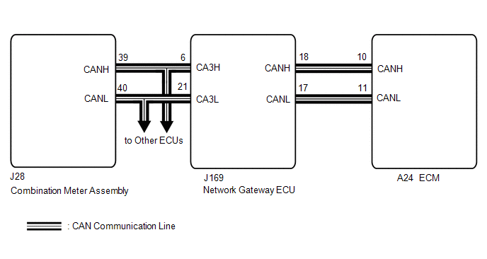 PROCEDURE
(a) Perform troubleshooting in accordance with the table below.
(a) Connect the Techstream to the DLC3. (b) Turn the ignition switch to ON. (c) Turn the Techstream on. (d) Check the communication between the Techstream and ECM. HINT: Communication can be checked by using the Data List item Engine.
(a) Connect the Techstream to the DLC3. (b) Turn the ignition switch to ON. (c) Turn the Techstream on. (d) Enter the following menus: System Select / Health Check. (e) Check if any DTCs have been detected. Note down any DTCs.
HINT: Check for detected DTCs output from other ECUs which relate to the MIL.
(a) Connect the Techstream to the DLC3. (b) Turn the ignition switch to ON. (c) Turn the Techstream on. (d) Enter the following menus: Body Electrical / Combination Meter / Active Test / Check Engine Indicator. Body Electrical > Combination Meter > Active Test
(e) According to the display on the Techstream, perform the Active Test and check the operation of the MIL.
|
Toyota Tundra Service Manual > Automatic Transmission Fluid: Replacement
REPLACEMENT PROCEDURE 1. REPLACE AUTOMATIC TRANSMISSION FLUID (a) Lift the vehicle. [*1] NOTICE: Set the vehicle on a lift so that the vehicle is kept level when it is lifted up (make sure that the tilt angle from the front to rear of the vehicle is within +/-1°). (b) Remove the drain plug and gask ...


