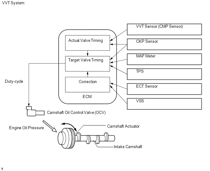
DESCRIPTION The VVT system
includes the ECM, Oil Control Valve (OCV) and VVT controller. The ECM
sends a target duty-cycle control signal to the OCV. This control signal
regulates the oil pressure supplied to the VVT controller. Camshaft
timing control is performed according to engine operating conditions
such as the intake air volume, throttle valve position and engine
coolant temperature. The ECM controls the OCV based on the signals
transmitted by several sensors. The VVT controller regulates the intake
camshaft angle using oil pressure through the OCV. As a result, the
relative positions of the camshaft and crankshaft are optimized, the
engine torque and fuel economy improve, and the exhaust emissions
decrease under overall driving conditions. The ECM detects the actual
intake valve timing using signals from the camshaft and crankshaft
position sensors, and performs feedback control. This is how the target
intake valve timing is verified by the ECM.
 |
DTC No. | DTC Detection Condition |
Trouble Area | | P0011
P0021 | Intake valve timing is not adjusted in valve timing advance range
(1 trip detection logic) |
- Valve timing
- OCV (for intake side of bank 1, 2)
- OCV filter
- Camshaft timing gear assembly
- ECM
| | P0012
P0022 | Intake valve timing is not adjusted in valve timing retard range
(2 trip detection logic) |
- Valve timing
- OCV (for intake side of bank 1, 2)
- OCV filter
- Camshaft timing gear assembly
- ECM
| MONITOR DESCRIPTION
- The ECM optimizes the intake valve timing using the VVT (Variable Valve
Timing) system to control the intake camshaft. The VVT system includes
the ECM, Oil Control Valve (OCV) and VVT controller. The ECM sends a
target duty-cycle control signal to the OCV. This control signal
regulates the oil pressure supplied to the VVT controller. The VVT
controller can advance or retard the intake camshaft.
- If the difference between the target and actual intake valve timings is
large, and changes in the actual intake valve timing are small, the ECM
interprets this as a VVT controller stuck malfunction and stores a DTC.
- Example:
- A DTC is stored when the following conditions 1 and 2 are met:
- 1. It takes 5 seconds or more to change the valve timing by 5°CA.
- 2. After the above condition 1 is met, the camshaft timing oil control valve is forcibly activated for 10 seconds.
- DTC P0011 and P0021 (Advanced Cam Timing) are subject to 1 trip detection logic.
- DTC P0012 and P0022 (Retarded Cam Timing) are subject to 2 trip detection logic.
- These DTCs indicate that the VVT controller cannot operate properly due
to OCV malfunctions or the presence of foreign objects in the OCV.
MONITOR STRATEGY |
Related DTCs | P0011: Advanced camshaft timing (for Bank 1)
P0012: Retarded camshaft timing (for Bank 1) P0021: Advanced camshaft timing (for Bank 2)
P0022: Retarded camshaft timing (for Bank 2) | |
Required Sensors/Components (Main) | VVT OCV and VVT Actuator | |
Required Sensors/Components (Related) |
Crankshaft position sensor, Camshaft position sensor and Engine coolant temperature sensor | |
Frequency of Operation | Continuous | |
Duration | Within 10 seconds | |
MIL Operation | Advanced camshaft timing: Immediate
Retarded camshaft timing: 2 driving cycles | |
Sequence of Operation | None | TYPICAL ENABLING CONDITIONS |
Monitor runs whenever following DTCs not present | P0010, P0020 (VVT oil control valve)
P0016, P0018 (VVT system - Misalignment) P0102, P0103 (Mass air flow meter)
P0107, P0108 (Manifold absolute pressure) P0115, P0117, P0118 (Engine coolant temperature sensor)
P0125 (Insufficient Coolant Temperature for Closed Loop Fuel Control)
P0335 (Crankshaft position sensor) P1340 (Camshaft position sensor) | |
Battery voltage | 11 V or more | |
Engine RPM | 500 to 4000 rpm | |
ECT | 75 to 100°C (167 to 212°F) | TYPICAL MALFUNCTION THRESHOLDS Advanced Camshaft Timing |
All conditions are met: | - | |
Deviation of actual valve timing and target valve timing |
More
than 5°CA (Crankshaft Angle) for 5 seconds or more after the VVT hold
duty ratio learned value reaches the upper or lower limit. | |
Valve timing | No change at advanced valve timing | Retarded Camshaft Timing |
All conditions are met: | - | |
Deviation of actual valve timing and target valve timing |
More
than 5°CA (Crankshaft Angle) for 5 seconds or more after the VVT hold
duty ratio learned value reaches the upper or lower limit. | |
Valve timing | No change at retarded valve timing |
- If the difference between the target and actual camshaft timings is
greater than the specified value, the ECM operates the VVT actuator.
- Then, the ECM monitors the camshaft timing change for 10 seconds.
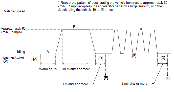
CONFIRMATION DRIVING PATTERN
- Connect the Techstream to the DLC3.
- Turn the ignition switch to ON and turn the Techstream on.
- Clear the DTCs (even if no DTCs are stored, perform the clear DTC operation).
- Turn the ignition switch off and wait for at least 30 seconds.
- Turn the ignition switch to ON and turn the Techstream on [A].
- Start the engine and warm it up until the ECT reaches 75°C (167°F) or higher [B].
- Drive the vehicle at approximately 60 km/h (37 mph) for 10 minutes or more [C].
CAUTION:
When performing the confirmation driving pattern, obey all speed limits and traffic laws.
- Idle the engine for 3 minutes or more [D].
- Enter the following menus: Powertrain / Engine and ECT / Trouble Codes [E].
- Read the pending DTCs.
HINT:
- If a pending DTC is output, the system is malfunctioning.
- If a pending DTC is not output, perform the following procedure.
- Enter the following menus: Powertrain / Engine and ECT / Utility / All Readiness.
- Input the DTC: P0011, P0012, P0021 or P0022.
- Check the DTC judgment result.
|
Techstream Display |
Description |
|
NORMAL |
- DTC judgment completed
- System normal
|
|
ABNORMAL |
- DTC judgment completed
- System abnormal
|
|
INCOMPLETE |
- DTC judgment not completed
- Perform driving pattern after confirming DTC enabling conditions
|
|
N/A |
- Unable to perform DTC judgment
- Number of DTCs which do not fulfill DTC preconditions has reached ECU memory limit
|
HINT:
- If the judgment result shows NORMAL, the system is normal.
- If the judgment result shows ABNORMAL, the system has a malfunction.
- If the judgment result shows INCOMPLETE or N/A, perform steps [F] through [H].
- Repeat the pattern of accelerating the vehicle from rest to
approximately 60 km/h (37 mph) and then decelerating the vehicle 10 to
15 times [F].
CAUTION:
When performing the confirmation driving pattern, obey all speed limits and traffic laws.
HINT:
Depress the accelerator pedal by a large amount.
- Idle the engine for 3 minutes or more [G].
- Enter the following menus: Powertrain / Engine and ECT / Trouble Codes [H].
- Read the pending DTCs.
HINT:
- If a pending DTC is output, the system is malfunctioning.
- If a pending DTC is not output, perform the following procedure.
- Check the DTC judgment result again.
HINT:
- If the judgment result shows NORMAL, the system is normal.
- If the judgment result shows ABNORMAL, the system has a malfunction.
- If the judgment result shows INCOMPLETE or N/A, perform the following procedure.
- Perform a universal trip and check for permanent DTCs (See page
 ). ).
HINT:
- If a permanent DTC is output, the system is malfunctioning.
- If no permanent DTC is output, the system is normal.
WIRING DIAGRAM Refer to DTC P0010 (See page
). CAUTION / NOTICE / HINT
HINT: DTC
P0011, P0012, P0021 or P0022 may be set when foreign objects in the
engine oil are caught in some parts of the system. The DTC will remain
set even if the system returns to normal after a short time. Foreign
objects are filtered out by the oil filter. |
Abnormal Bank | Advanced Timing Over
(Valve Timing is Out of Specified Range) |
Retarded Timing Over (Valve Timing is Out of Specified Range) | |
Bank 1 | P0011 |
P0012 | | Bank 2 |
P0021 | P0022 |
PROCEDURE |
1. | CHECK ANY OTHER DTCS OUTPUT (IN ADDITION TO DTC P0011, P0012, P0021 OR P0022) |
(a) Connect the Techstream to the DLC3. (b) Turn the ignition switch to ON.
(c) Turn the Techstream on. (d) Enter the following menus: Powertrain / Engine and ECT / Trouble Codes.
(e) Read DTCs. Result |
Result | Proceed to | |
P0011, P0012, P0021 or P0022 is output |
A | | P0011, P0012, P0021 or P0022 and other DTCs are output |
B | HINT: If any DTCs other than P0011, P0012, P0021 or P0022 are output, troubleshoot those DTCs first.
| B |
 | GO TO DTC CHART |
|
A |
 | |
| 2. |
PERFORM ACTIVE TEST USING TECHSTREAM (OPERATE OCV) |
(a) Connect the Techstream to the DLC3. (b) Start the engine and turn the Techstream on.
(c) Warm up the engine. (d)
Enter the following menus: Powertrain / Engine and ECT / Active Test /
Control the VVT Linear (Bank 1) or Control the VVT Linear (Bank 2). (e) Check the engine speed while operating the camshaft oil control valve using the Techstream.
OK: |
Techstream Operation | Engine Condition | |
0% | Normal engine speed | |
100% | Engine idles roughly or stalls |
| NG |
| GO TO STEP 4 |
|
OK | |
| |
| 3. |
CHECK WHETHER DTC OUTPUT RECURS (DTC P0011, P0012, P0021 OR P0022) |
(a) Connect the Techstream to the DLC3. (b) Turn the ignition switch to ON.
(c) Turn the Techstream on. (d) Clear DTCs (See page
). (e) Start the engine and warm it up.
(f) Drive the vehicle in accordance with the driving pattern described in the Confirmation Driving Pattern.
(g) Read the output pending DTCs using the Techstream. OK: No pending DTC output.
| OK |
| CHECK FOR INTERMITTENT PROBLEMS |
|
NG | |
| |
| 4. |
CHECK VALVE TIMING (CHECK FOR LOOSENESS IN TIMING CHAIN OR JUMPED TOOTH) |
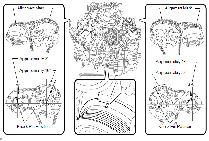 (a) Remove the cylinder head cover LH and RH.
(b) Turn the crankshaft pulley, and align its groove with the alignment mark "0" of the timing chain cover.
(c)
Check that the alignment marks of the camshaft timing gears and
camshaft timing exhaust gears are at the positions shown in the
illustration.
HINT:
- If the alignment marks are not as shown, turn the crankshaft one revolution clockwise.
- If the result is not as specified, check mechanical parts related to
valve timing for looseness in the timing chain, jumped teeth, etc.
OK: Alignment marks on camshaft timing gears are aligned as shown in the illustration.
| NG |
| CHECK ENGINE MECHANICAL SYSTEM |
|
OK | |
| |
| 5. |
INSPECT CAMSHAFT OIL CONTROL VALVE ASSEMBLY (OCV) |
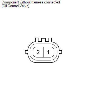 (a) Remove the OCV. (b) Measure the resistance according to the value(s) in the table below.
Standard Resistance: |
Tester Connection | Condition |
Specified Condition | |
1 - 2 | 20°C (68°F) |
6.9 to 7.9 Ω |
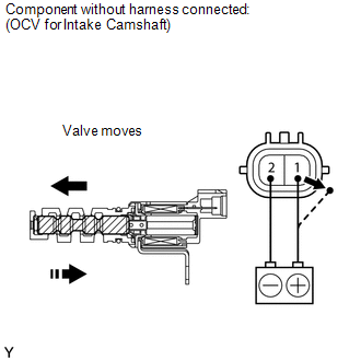 (c) Apply positive (+) battery voltage to terminal 1 and negative (-) battery voltage to terminal 2. Check the valve operation.
OK: Valve moves quickly.
| NG | |
REPLACE CAMSHAFT OIL CONTROL VALVE ASSEMBLY |
|
OK | |
| |
| 6. |
INSPECT OIL CONTROL VALVE FILTER | (a) Remove the OCV filter (See page
). (b) Check that the filter is not clogged.
OK: Filter is not clogged.
| NG |
| CLEAN OIL CONTROL VALVE FILTER |
|
OK | |
| |
| 7. |
REPLACE CAMSHAFT TIMING GEAR ASSEMBLY |
(a) Replace the camshaft timing gear assembly (See page
). HINT: Perform "Inspection After Repair" after replacing the camshaft timing gear assembly (See page
).
|
NEXT | |
| |
| 8. |
CHECK WHETHER DTC OUTPUT RECURS | (a) Connect the Techstream to the DLC3.
(b) Turn the ignition switch to ON. (c) Turn the Techstream on.
(d) Clear DTCs (See page ). (e) Start the engine and warm it up.
(f) Drive the vehicle in accordance with the driving pattern described in the Confirmation Driving Pattern.
(g) Read the output pending DTCs using the Techstream. OK: No pending DTC is output.
HINT: DTC
P0011, P0012, P0021 or P0022 is output when foreign objects in the
engine oil are caught in some parts of the system. These codes will stay
registered even if the system returns to normal after a short time.
These foreign objects are then captured by the oil filter, thus
eliminating the source of the problem.
| OK |
| END |
| NG |
| REPLACE ECM | |


