DESCRIPTION A thermistor, whose resistance value varies according to the ECT, is built into the Engine Coolant Temperature (ECT) sensor. The structure of the sensor and its connection to the ECM are the same as those of the Intake Air Temperature (IAT) sensor. HINT: When DTC P0115, P0117 or P0118 is stored, the ECM enters fail-safe mode. During fail-safe mode, the ECT is estimated to be 80°C (176°F) by the ECM. Fail-safe mode continues until a pass condition is detected.
HINT: When any of these DTCs are stored, check the ECT by entering the following menus: Powertrain / Engine and ECT / Data List / Coolant Temp.
MONITOR DESCRIPTION The Engine Coolant Temperature (ECT) sensor is used to monitor the ECT. The ECT sensor has a thermistor with a resistance that varies according to the temperature of the engine coolant. When the coolant temperature is low, the resistance in the thermistor increases. When the temperature is high, the resistance drops. These variations in resistance are reflected in the output voltage from the sensor. The ECM monitors the sensor voltage and uses this value to calculate the ECT. When the sensor output voltage deviates from the normal operating range, the ECM interprets this as a fault in the ECT sensor and stores a DTC. Example: If the sensor output voltage is more than 4.91 V for 0.5 seconds or more, the ECM determines that there is an open in the ECT sensor circuit, and stores DTC P0118. Conversely, if the voltage output is less than 0.14 V for 0.5 seconds or more, the ECM determines that there is a short in the sensor circuit, and stores DTC P0117. If the malfunction is not repaired successfully, a DTC is stored 0.5 seconds after the engine is next started. MONITOR STRATEGY
TYPICAL ENABLING CONDITIONS
TYPICAL MALFUNCTION THRESHOLDS P0115
COMPONENT OPERATING RANGE
CONFIRMATION DRIVING PATTERN
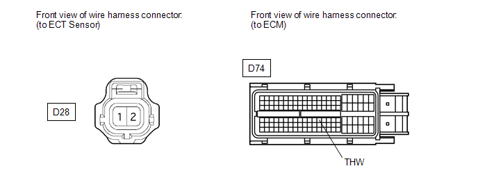
WIRING DIAGRAM 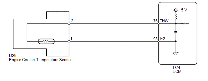 CAUTION / NOTICE / HINT HINT: Read freeze frame data using the Techstream. Freeze frame data records the engine condition when malfunctions are detected. When troubleshooting, freeze frame data can help determine if the vehicle was moving or stationary, if the engine was warmed up or not, if the air-fuel ratio was lean or rich, and other data from the time the malfunction occurred. PROCEDURE
(a) Connect the Techstream to the DLC3. (b) Turn the ignition switch to ON. (c) Turn the Techstream on. (d) Enter the following menus: Powertrain / Engine and ECT / Data List / Coolant Temp. (e) Read the value displayed on the Techstream. Standard value: Between 75 and 100°C (167 and 212°F) with warm engine. Result
HINT:
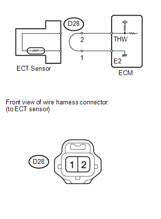 (a) Disconnect the ECT sensor connector. (b) Connect terminals 1 and 2 of the ECT sensor connector on the wire harness side. (c) Connect the Techstream to the DLC3. (d) Turn the ignition switch to ON. (e) Turn the Techstream on. (f) Enter the following menus: Powertrain / Engine and ECT / Data List / Coolant Temp. (g) Read the value displayed on the Techstream. Standard value: 140°C (284°F) or higher HINT: Perform "Inspection After Repair" after replacing the engine coolant temperature sensor (See page
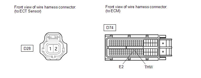 (a) Disconnect the ECT sensor connector. (b) Disconnect the ECM connector. (c) Measure the resistance according to the value(s) in the table below. Standard Resistance:
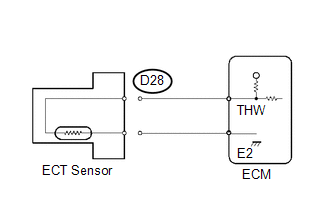 (a) Disconnect the ECT sensor connector. (b) Connect the Techstream to the DLC3. (c) Turn the ignition switch to ON. (d) Turn the Techstream on. (e) Enter the following menus: Powertrain / Engine and ECT / Data List / Coolant Temp. (f) Read the value displayed on the Techstream. Standard value: -40°C (-40°F) HINT: Perform "Inspection After Repair" after replacing the engine coolant temperature sensor (See page
 (a) Disconnect the ECT sensor connector. (b) Disconnect the ECM connector. (c) Measure the resistance according to the value(s) in the table below. Standard Resistance:
|
Toyota Tundra Owners Manual > Opening, closing the
windows and moon roof: Power windows
Opening and closing procedures The power windows can be opened and closed using the switches. Operating the switch moves the windows as follows: Type A Closing Opening One-touch opening* (driver's window only) *: To stop the window partway, operate the switch in the opposite direction. Type B Closin ...

 ).
).


