DESCRIPTION
HINT:
- These DTCs indicate malfunctions relating to the primary circuit.
- If DTC P0351 is stored, check the No. 1 ignition coil circuit.
- If DTC P0352 is stored, check the No. 2 ignition coil circuit.
- If DTC P0353 is stored, check the No. 3 ignition coil circuit.
- If DTC P0354 is stored, check the No. 4 ignition coil circuit.
- If DTC P0355 is stored, check the No. 5 ignition coil circuit.
- If DTC P0356 is stored, check the No. 6 ignition coil circuit.
- If DTC P0357 is stored, check the No. 7 ignition coil circuit.
- If DTC P0358 is stored, check the No. 8 ignition coil circuit.
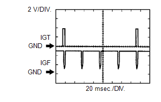
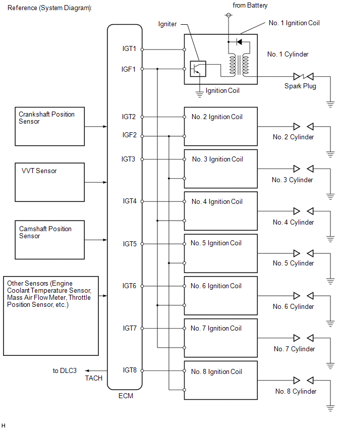
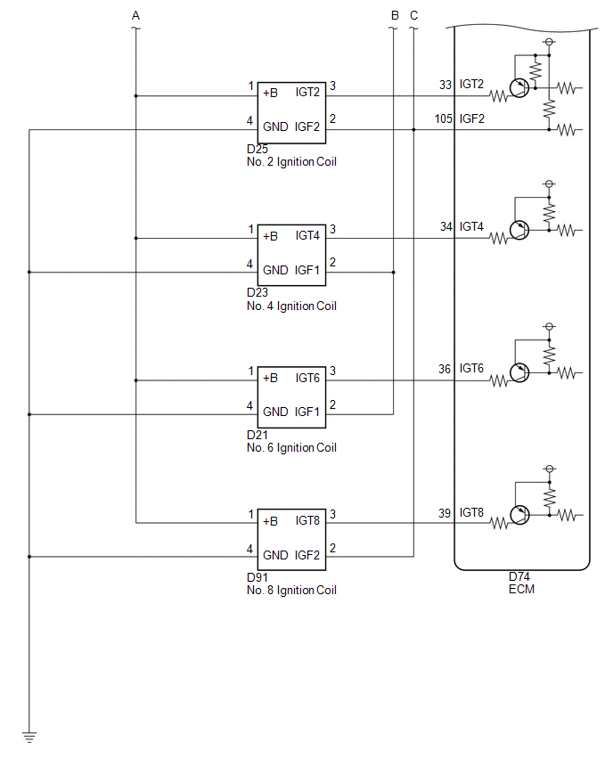
A Direct Ignition System (DIS) is used on this vehicle. The
DIS is a 1-cylinder ignition system in which each cylinder is ignited
by one ignition coil and one spark plug is connected to the end of each
secondary wiring. A powerful voltage, generated in the secondary wiring,
is applied directly to each spark plug. The sparks of the spark plugs
pass from the center electrode to the ground electrodes. The
ECM determines the ignition timing and transmits the ignition (IGT)
signals to each cylinder. Using the IGT signal, the ECM turns the power
transistor inside the igniter on and off. The power transistor, in turn,
switches on and off the current to the primary coil. When the current
to the primary coil is cut off, a powerful voltage is generated in the
secondary coil. This voltage is applied to the spark plugs, causing them
to spark inside the cylinders. As the ECM cuts the current to the
primary coil, the igniter sends back an ignition confirmation (IGF)
signal to the ECM for each cylinder ignition.
 |
DTC No. | DTC Detection Condition |
Trouble Area | | P0351
P0352 P0353 P0354 P0355 P0356 P0357
P0358 | No IGF signal to ECM while engine running
(1 trip detection logic) |
- Ignition system
- Open or short in IGF or IGT circuit (1 to 8) between ignition coil and ECM
- No. 1 to No. 8 ignition coils
- ECM
|
MONITOR DESCRIPTION
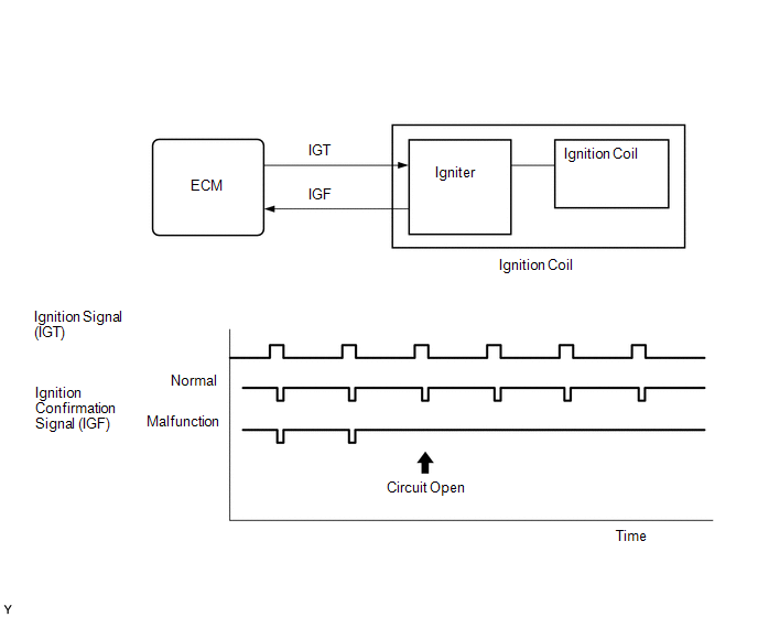 If
the ECM does not receive any IGF signals despite transmitting the IGT
signal, it interprets this as a fault in the igniter and stores a DTC. If the malfunction is not repaired successfully, a DTC is stored 1 second after the engine is next started. MONITOR STRATEGY |
Related DTCs | P0351: Igniter (cylinder 1) malfunction
P0352: Igniter (cylinder 2) malfunction P0353: Igniter (cylinder 3) malfunction
P0354: Igniter (cylinder 4) malfunction P0355: Igniter (cylinder 5) malfunction
P0356: Igniter (cylinder 6) malfunction P0357: Igniter (cylinder 7) malfunction
P0358: Igniter (cylinder 8) malfunction | |
Required Sensors/Components (Main) | Igniter | |
Required Sensors/Components (Related) |
Crankshaft position sensor | |
Frequency of Operation | Continuous | |
Duration | 0.256 seconds | |
MIL Operation | Immediate | |
Sequence of Operation | None | TYPICAL ENABLING CONDITIONS |
Monitor runs whenever following DTCs not present |
None | | Either of following conditions A or B met |
- | | A. Engine RPM |
1500 rpm or less | | B. Starter |
OFF | | Either of following conditions C or D met |
- | | C. Both of following conditions (a) and (b) met |
- | | (a) Engine speed |
500 rpm or less | | (b) Battery voltage |
6 V or more | | D. All of following conditions (a), (b) and (c) met |
- | | (a) Engine speed |
More than 500 rpm | | (b) Battery voltage |
10 V or more | | (c) Number of sparks after CPU reset |
5 sparks or more | TYPICAL MALFUNCTION THRESHOLDS |
All of the following conditions are met |
A. B. C and D | | A. Ignition signal fail counter |
More than 2 times | | B. Time after condition A is met |
0.256 seconds or more | | C. Ignition signal fail count after condition B is met |
More than 2 times | | D. Ignition switch |
ON | COMPONENT OPERATING RANGE |
IGF signal | Igniter transmits IGF signal when it receives IGT signal from ECM | CONFIRMATION DRIVING PATTERN
- Connect the Techstream to the DLC3.
- Turn the ignition switch to ON and turn the Techstream on.
- Clear DTCs (even if no DTCs are stored, perform the clear DTC operation).
- Turn the ignition switch off and wait for at least 30 seconds.
- Turn the ignition switch to ON and turn the Techstream on.
- Start the engine.
- Idle the engine for 10 seconds or more [A].
- Enter the following menus: Powertrain / Engine and ECT / Trouble Codes [B].
- Read the pending DTCs.
HINT:
- If a pending DTC is output, the system is malfunctioning.
- If a pending DTC is not output, perform the following procedure.
- Enter the following menus: Powertrain / Engine and ECT / Utility / All Readiness.
- Input the DTC: P0351, P0352, P0353, P0354, P0355, P0356, P0357 or P0358.
- Check the DTC judgment result.
|
Tester Display |
Description |
|
NORMAL |
- DTC judgment completed
- System normal
|
|
ABNORMAL |
- DTC judgment completed
- System abnormal
|
|
INCOMPLETE |
- DTC judgment not completed
- Perform driving pattern after confirming DTC enabling conditions
|
|
N/A |
- Unable to perform DTC judgment
- Number of DTCs which do not fulfill DTC preconditions has reached ECU memory limit
|
HINT:
- If the judgment result shows ABNORMAL, the system has a malfunction.
- If the judgment result shows INCOMPLETE or N/A, perform steps [A] through [B] again.
- If no pending DTC is output, perform a universal trip and check for permanent DTCs (See page
 ). ).
HINT:
- If a permanent DTC is output, the system is malfunctioning.
- If no permanent DTC is output, the system is normal.
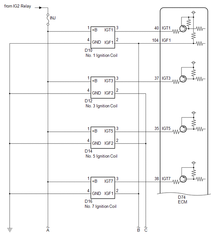
WIRING DIAGRAM
 CAUTION / NOTICE / HINT
HINT: Read
freeze frame data using the Techstream. Freeze frame data records the
engine condition when malfunctions are detected. When troubleshooting,
freeze frame data can help determine if the vehicle was moving or
stationary, if the engine was warmed up or not, if the air-fuel ratio
was lean or rich, and other data from the time the malfunction occurred. PROCEDURE
| 1. |
INSPECT IGNITION COIL ASSEMBLY (POWER SOURCE) |
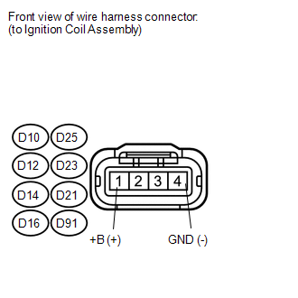 (a) Disconnect the ignition coil assembly connector.
(b) Measure the resistance according to the value(s) in the table below.
Standard Resistance: |
Tester Connection | Condition |
Specified Condition | |
D10-4 (GND) - Body ground |
Always | Below 1 Ω | |
D25-4 (GND) - Body ground |
Always | Below 1 Ω | |
D12-4 (GND) - Body ground |
Always | Below 1 Ω | |
D23-4 (GND) - Body ground |
Always | Below 1 Ω | |
D14-4 (GND) - Body ground |
Always | Below 1 Ω | |
D21-4 (GND) - Body ground |
Always | Below 1 Ω | |
D16-4 (GND) - Body ground |
Always | Below 1 Ω | |
D91-4 (GND) - Body ground |
Always | Below 1 Ω |
(c) Turn the ignition switch to ON. (d) Measure the voltage according to the value(s) in the table below.
Standard Voltage: |
Tester Connection | Switch Condition |
Specified Condition | |
D10-1 (+B) - D10-4 (GND) |
Ignition switch ON | 11 to 14 V | |
D25-1 (+B) - D25-4 (GND) |
Ignition switch ON | 11 to 14 V | |
D12-1 (+B) - D12-4 (GND) |
Ignition switch ON | 11 to 14 V | |
D23-1 (+B) - D23-4 (GND) |
Ignition switch ON | 11 to 14 V | |
D14-1 (+B) - D14-4 (GND) |
Ignition switch ON | 11 to 14 V | |
D21-1 (+B) - D21-4 (GND) |
Ignition switch ON | 11 to 14 V | |
D16-1 (+B) - D16-4 (GND) |
Ignition switch ON | 11 to 14 V | |
D91-1 (+B) - D91-4 (GND) |
Ignition switch ON | 11 to 14 V |
| NG |
 | REPAIR OR REPLACE HARNESS OR CONNECTOR |
|
OK |
 | |
| 2. |
CHECK HARNESS AND CONNECTOR (IGNITION COIL ASSEMBLY - ECM) |
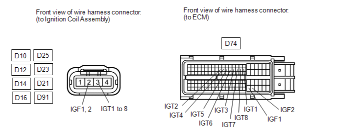 (a) Disconnect the ignition coil assembly connector.
(b) Disconnect the ECM connector. (c) Measure the resistance according to the value(s) in the table below.
Standard Resistance: |
Tester Connection | Condition |
Specified Condition | |
D10-2 (IGF1) - D74-104 (IGF1) |
Always | Below 1 Ω | |
D25-2 (IGF2) - D74-105 (IGF2) |
Always | Below 1 Ω | |
D12-2 (IGF2) - D74-105 (IGF2) |
Always | Below 1 Ω | |
D23-2 (IGF1) - D74-104 (IGF1) |
Always | Below 1 Ω | |
D14-2 (IGF2) - D74-105 (IGF2) |
Always | Below 1 Ω | |
D21-2 (IGF1) - D74-104 (IGF1) |
Always | Below 1 Ω | |
D16-2 (IGF1) - D74-104 (IGF1) |
Always | Below 1 Ω | |
D91-2 (IGF2) - D74-105 (IGF2) |
Always | Below 1 Ω | |
D10-3 (IGT1) - D74-40 (IGT1) |
Always | Below 1 Ω | |
D25-3 (IGT2) - D74-33 (IGT2) |
Always | Below 1 Ω | |
D12-3 (IGT3) - D74-37 (IGT3) |
Always | Below 1 Ω | |
D23-3 (IGT4) - D74-34 (IGT4) |
Always | Below 1 Ω | |
D14-3 (IGT5) - D74-35 (IGT5) |
Always | Below 1 Ω | |
D21-3 (IGT6) - D74-36 (IGT6) |
Always | Below 1 Ω | |
D16-3 (IGT7) - D74-38 (IGT7) |
Always | Below 1 Ω | |
D91-3 (IGT8) - D74-39 (IGT8) |
Always | Below 1 Ω | |
D10-2 (IGF1) or D74-104 (IGF1) - Body ground |
Always | 10 kΩ or higher | |
D25-2 (IGF2) or D74-105 (IGF2) - Body ground |
Always | 10 kΩ or higher | |
D12-2 (IGF2) or D74-105 (IGF2) - Body ground |
Always | 10 kΩ or higher | |
D23-2 (IGF1) or D74-104 (IGF1) - Body ground |
Always | 10 kΩ or higher | |
D14-2 (IGF2) or D74-105 (IGF2) - Body ground |
Always | 10 kΩ or higher | |
D21-2 (IGF1) or D74-104 (IGF1) - Body ground |
Always | 10 kΩ or higher | |
D16-2 (IGF1) or D74-104 (IGF1) - Body ground |
Always | 10 kΩ or higher | |
D91-2 (IGF2) or D74-105 (IGF2) - Body ground |
Always | 10 kΩ or higher | |
D10-3 (IGT1) or D74-40 (IGT1) - Body ground |
Always | 10 kΩ or higher | |
D25-3 (IGT2) or D74-33 (IGT2) - Body ground |
Always | 10 kΩ or higher | |
D12-3 (IGT3) or D74-37 (IGT3) - Body ground |
Always | 10 kΩ or higher | |
D23-3 (IGT4) or D74-34 (IGT4) - Body ground |
Always | 10 kΩ or higher | |
D14-3 (IGT5) or D74-35 (IGT5) - Body ground |
Always | 10 kΩ or higher | |
D21-3 (IGT6) or D74-36 (IGT6) - Body ground |
Always | 10 kΩ or higher | |
D16-3 (IGT7) or D74-38 (IGT7) - Body ground |
Always | 10 kΩ or higher | |
D91-3 (IGT8) or D74-39 (IGT8) - Body ground |
Always | 10 kΩ or higher |
| NG |
| REPAIR OR REPLACE HARNESS OR CONNECTOR |
|
OK | |
| |
| 3. |
CHECK WHETHER DTC OUTPUT RECURS (DTC P0351, P0352, P0353, P0354, P0355, P0356, P0357 OR P0358) |
(a) Connect the Techstream to the DLC3. (b) Turn the ignition switch to ON.
(c) Turn the Techstream on. (d) Clear DTCs (See page
). (e) Shuffle the arrangement of the ignition coil assemblies (among No. 1 to No. 8 cylinders).
NOTICE: Do not shuffle the connectors. (f) Drive the vehicle in accordance with the driving pattern described in the Confirmation Driving Pattern.
(g) Check DTCs displayed on the Techstream. Result |
Result | Proceed to | |
Same DTC is output | A | |
Different ignition coil DTC is output |
B | HINT: Perform "Inspection After Repair" after replacing the ignition coil assembly (See page
).
| A | |
REPLACE ECM |
| B |
| REPLACE IGNITION COIL ASSEMBLY | |